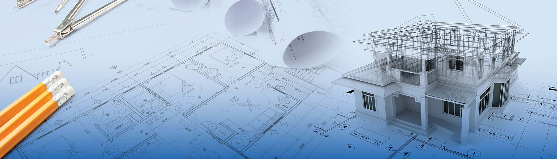

- Architectural drawing types like floor plans, site plans, sections, and elevations help architects transform design intent into planned construction.
- Firms stuck with obsolete drafting techniques and tools create error-prone deliverables that drain valuable project time.
- BIM provides the workflows and required toolset to overcome architectural drawing issues using precise, information-rich, and intelligent 3D models.
Table of Contents
Precise and scaled visualization using architectural drawings helps architects and other stakeholders understand design intent. These drawings include detail drawings, structural drawings, perspective drawings, and other 2D plans that help communicate design dimensions, material selection, spatial relationships, and refined strategies. Architectural technical drawings also help engineering companies and fabrication firms manufacture building components that align perfectly during construction.
Drafting of plans using legacy tools leads to multiple issues, which include file versioning hurdles, inaccurate views, and inconsistent coordination in early design. Utilizing hand sketches also causes gaps in team communication and fragmented documentation, leading to design problems, costly rework, and extended timelines.
Architectural drawings extracted from coordinated and clash-free 3D models prevent manual errors and promote collaboration. It enables faster automation of views within drawings using parametric modeling, dynamic updates, and customized workflows.

Role of the top 10 architectural drawing types in design and construction.
Architectural drawings utilized at various stages of design, manufacturing, and construction provide significant advantages for project participants. They inform of parameters like building dimensions, layouts, finishes, and materials for various phases of the building lifecycle. These precise drawings help architects and other teams coordinate better, reduce errors and speed up project approvals.
1. Site plans
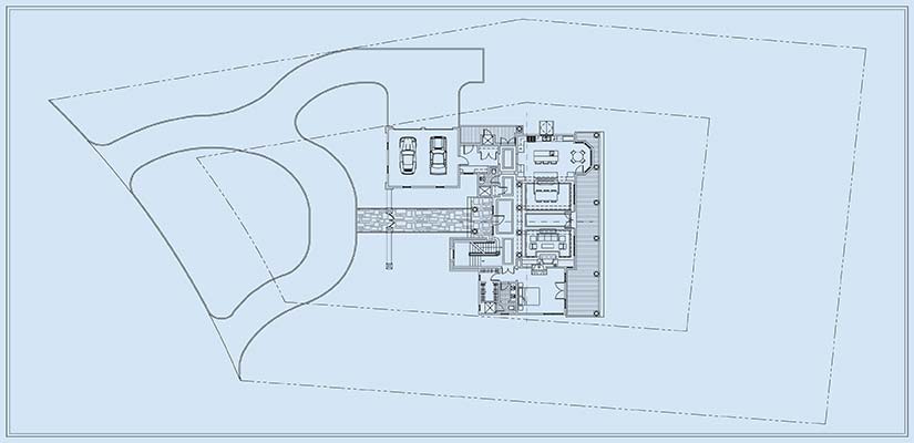
Site plans are used to pinpoint the building location while defining access roads, landscapes, utilities, and boundaries. They are used for improving spatial planning, adhering to zoning laws, and verifying environmental limits before actual construction begins.
Boundaries within site plans include structural placement and the accurate delineation of property features. Site plans also include landscape data for vegetation cover and drainage systems. Topographic data in these drawings help architects visualize slopes, elevations, and contour lines for stormwater management and accurate grading. These plans play a crucial role in construction planning and the clearance of legal documentation. Their roles include:
- Assess access roads, building locations, and parking areas.
- Expedite approvals.
- Prevents risks in planned design.
- Facilitate legalities.
2. Floor plans
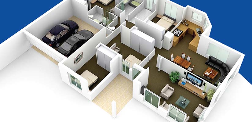
A floor plan includes multiple structural components, including walls, doors, rooms and windows in designated areas. These elements explain accessibility, air circulation, occupant movement and privacy in the entire building. Other elements may also include utilities, furniture positions and stairs. It helps architects with visualization of flow, space use, and architectural motives during actual work.
A floor plan provides a complete snapshot of structural elements, which include doors, walls, rooms and windows in planned spaces. These components help architectural firms visualize accessibility, circulation of air, occupant movement and scope within a building. Floor plans also encompass furniture locations, stairs, and various utilities. These drawings ensure spaces are functional and used as planned. They define geometric layouts and functionality, and their roles include:
- Determining relationships between access and circulation areas.
- Ensuring usability, safety, and spatial equilibrium.
- Enabling construction accuracy and data validity.
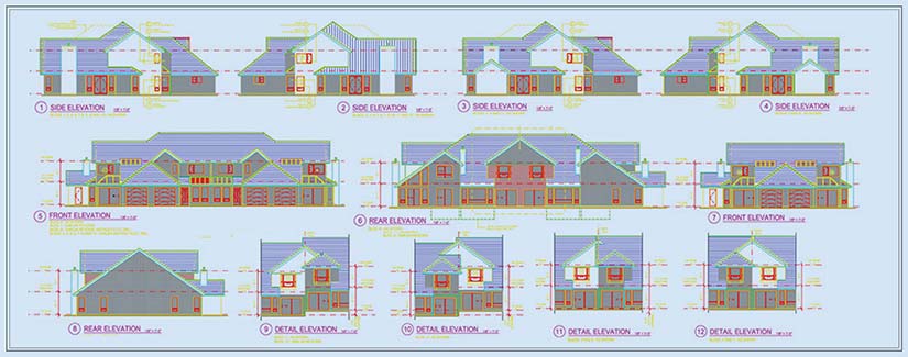
3. Elevation drawings
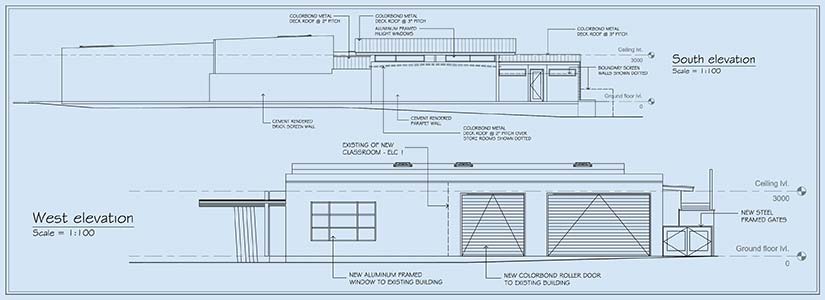
Elevation drawings are scaled and flat and represent a single side of a building using a vertical viewpoint. They incorporate exterior images for architectural elements, openings, materials and height. The use of elevations within construction illustrates building appearance, promotes visual coordination and defines accurate material specs.
These plans showcase the exterior building side, including doors, windows, materials, rooflines and the entire symmetry. Structural coordination is an important aspect of a building project. Aligning design elements in vertical views and across various floors ensures required coordination. Elevation drawings also illustrate architectural elements, including proportions, details, and facades, to realize aesthetics and technical accuracy during early-stage planning.
4. Section drawings
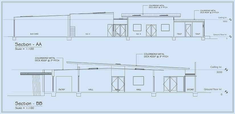
Section drawings illustrate cross-sections within a vertical format. Architects can visualize structural components, layouts, and elements, including beams, slabs, and various floor levels. Representing views through sliced angles, these drawings help identify spatial relationships and the technical alignment of elements.
These plans provide a complete snapshot of multiple layers, including acoustics, structure and thermal values. Built for visual clarity, these drawings minimize errors, enable coordination and provide high-quality detailing.
Expedite design approvals with accurate architectural drawings for building construction.
Transform your sketches into data-rich construction documents.
5. Detail drawings
Detail drawings include building components like sections, fixtures, walls, and joints while considering their dimensions and materials. These drawings enable architects to detect material overlapping, and they also describe methods to integrate tolerances and fastenings. This helps to actualize design intent and ensures every component is built as per project requirements.
Stakeholders, including architects, contractors, and engineers, can navigate through design complexities, verify material relations, and uphold compliance.
6. Structural drawings
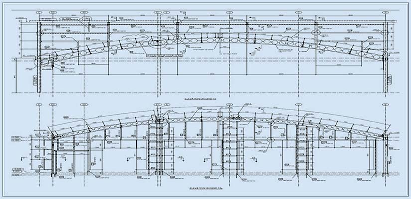
Structural drawings illustrate the entire building framework, which incorporates beams, columns, slabs and foundations. Onsite personnel use these plans for accurate load-bearing assembly, structural strength and occupant security.
Architects utilize these drawings to convey dimensions, reinforcement information, and required materials, while providing clarity on distributed and transferred forces. Accurate descriptions of the placement of members, sequencing, and reinforcement ensure structural stability, code compliance, and hassle-free on-site installation.
7. Mechanical, Electrical, and Plumbing (MEP) drawings
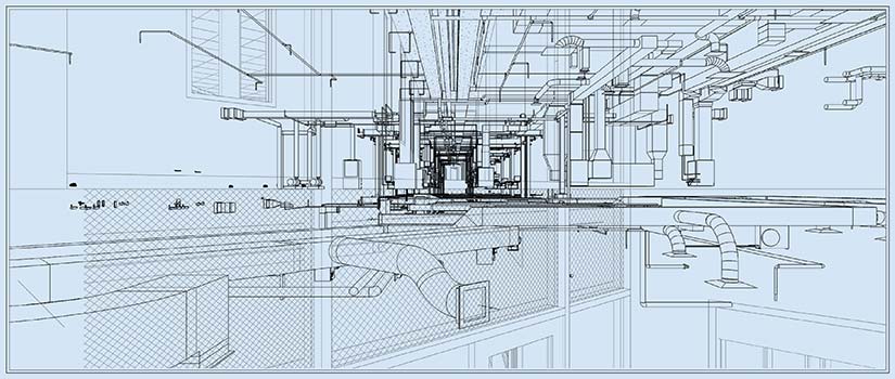
Accurate and detailed MEP drawings are technical representations of mechanical, electrical, and plumbing systems for a project. These drawings are crucial in buildings as they support stakeholders from multiple engineering disciplines, including MEP engineers, to realize functionality, safety, and faster integration with architectural and structural layouts.
MEP coordination plays a crucial role as these plans also incorporate details like equipment placement, MEP routing, and interconnecting MEP systems. The use of coordinated MEP drawings leads to lower rework, optimized space use, and ensures all parameters align with architectural and structural layouts for faster MEP installation.
8. Perspective drawings
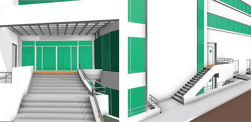
Buildings can be represented in 3D using perspective drawings. Using vanishing points provides depth and ensures clarity in appearance and spatial relationships.
Architectural elements are visualized with higher realism and scale, including texture and depth. Clients can gain a clear perspective on design intent using perspective drawings rather than obsolete 2D drawings. This leads to design validation and realistic visualization that enables engaging presentations and quick approvals during early-stage design.
9. Reflected ceiling plans
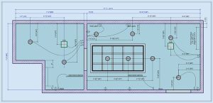
Reflected ceiling plans represent ceiling layouts. Accurate placement of elements, including lights, sprinklers, HVAC systems, air diffusers, etc., promotes coordination, design clarity, and error-free on-site installation. A comprehensive and clash-free view of these components helps teams assess access areas, component spacing, and their functionality.
Using these plans in the field ensures error-free installation, and that there is required equipment clearance, along with improvements in aesthetics and compliance with building codes.
10. Landscape drawings
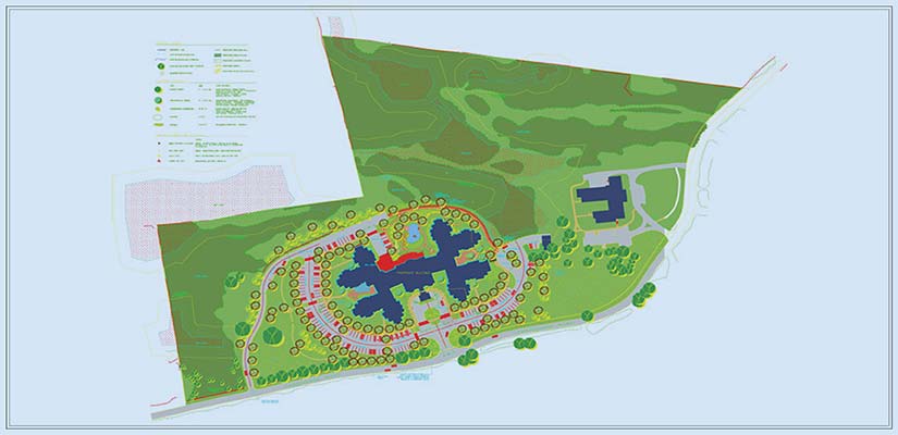
Landscape drawings provide a complete view of the outdoor sections, which include vegetation, pathways, and lighting. These drawings are key deliverables that represent synergy within natural surroundings and buildings for stormwater management, shading, and soil preservation. Architects using these plans can improve building aesthetics, element performance, and usability in the project.
Landscape drawings include the following elements:
- Shrubs
- Trees
- Walkways
- Lighting and water equipment
- Outdoor furniture
- Irrigation systems
How can architectural drawing services support architects and BIM/CAD professionals?
Architects and BIM professionals can outsource architectural drawing services for accurate and comprehensive plans using seamless BIM workflows. While architectural projects face hurdles, including extended design timelines, restricted project visibility and delayed approvals, architectural firms can navigate these challenges with precise and content-rich 3D models.
Architectural CAD drafting supports the creation of high-quality drawings through customized PDF to CAD conversion, construction documentation and Paper to CAD conversion solutions. Using these services ensures faster clash detection, improved collaboration, prevention of risks, time and cost optimization, and high-quality visualization in 3D space.
Coordinated shop drawings from clash-free models eliminate design issues.
An architectural firm from the US partnered with HitechDigital for a data center project. A 3D BIM model was created and handed over in the first phase. However, construction drawings were also required by the client’s team for development and we needed to generate them.
Files were imported into Revit to create a coordinated and clash-free 3D model. Clarifications and approvals were received from the client. The approved 3D model was used to extract the construction sheets and GFC drawings. The team at HitechDigital was also able to extract sections, plans, elevations, and IFC and approval drawings from the 3D model.
Handing over the deliverables to the client led to:
- Improved planning for onsite activities.
- Optimized on-site efficiency.
- Quick installation driven by clarity in drawing readability.
- Expedited design approvals from the local authority.
Conclusion
Architecture design and construction projects will continue to become more complex and increase in scale. Architectural firms, contractors, and engineers will thus always need architectural drawings that are error free, content driven, and enable improved visualization to prevent rework.
Bespoke architectural drawings created using Revit and AutoCAD will help streamline projects and lead to faster approvals. Whether it is architectural 3D drafting, PDF to CAD conversion, construction documentation, or the creation of project-wide drawings, architectural drafting services can help architects streamline workflows, ensure accuracy, and improve ROI for clients.
Facing challenges with inconsistent or unclear architectural drawings?
Access expert drafting services customized for your project.