
- Accurate sheet metal drafting is essential to avoid manufacturing errors and delays.
- Key best practices include clear component identification, precise bend allowance, and detailed hardware specifications.
- Also, consider material grain direction, document dimensions and tolerances, and adhere to DFM guidelines.
Table of Contents
- Follow clear component identification systems for sheet metal design accuracy
- Calculate bend allowance with precision during sheet metal drafting
- Clearly include hardware specifications in sheet metal drawings
- Carefully consider material grain direction during sheet metal drafting
- Be extra careful about documenting sheet metal dimensions and tolerances
- Adhere to Design for Manufacturing (DFM) guidelines
- Implement version control and change management for sheet metal drafting
- Wrapping up
Inaccurate sheet metal drafting leads to costly manufacturing errors, production delays and quality control issues. Poor dimensioning, unclear layouts and improper material specifications result in rejected parts and inefficient production cycles, affecting both designers and fabricators.
Here, we discuss seven essential sheet metal drafting best practices that comprehensively address these challenges. Implementing standardized dimensions, clear layouts with symbols, and precise material and hardware specifications help drafters create more accurate documentation.
In addition, leveraging CAD capabilities and strict adherence to DFM guidelines, along with systematic version control and peer reviews, provides a robust framework for quality control.
The guidelines we discuss here will help you avoid common mistakes in sheet metal drafting, optimize production time, and enhance communication between sheet metal design and fabrication teams.
Follow clear component identification systems for sheet metal design accuracy
A robust component identification system establishes unambiguous part tracking throughout the design and manufacturing processes. Each component receives a standardized alphanumeric code that follows a hierarchical structure, reflecting its position within the assembly and its relationship to other parts.
The identification system incorporates baseline data, including:
- Primary assembly designation
- Subassembly classification
- Individual part sequence
- Material grade indicators
- Thickness specifications
- Manufacturing process codes
For example, a typical sheet metal part number might be structured as:
SM-A01-P023-304-16G
Where, SM = Sheet Metal, A01 = Assembly Number, P023 = Part Number, 304 = Material Grade, 16G = Gauge Thickness
Digital drafting sheets display these identifiers in dedicated zones, typically the title block and part callouts. Barcode and QR codes can be integrated into the identification system for seamless tracking and revision control. Parametric modeling helps in sheet metal shop drawing accuracy by enabling automatic updates to component identification when design changes occur.
Component labels appear in multiple views to guarantee visibility during different manufacturing stages. The identification system links directly to the CAD database, enabling the automatic population of part information across related documents. Maintaining a standardized parts library ensures design consistency and simplified component management across projects.
Calculate bend allowance with precision during sheet metal drafting
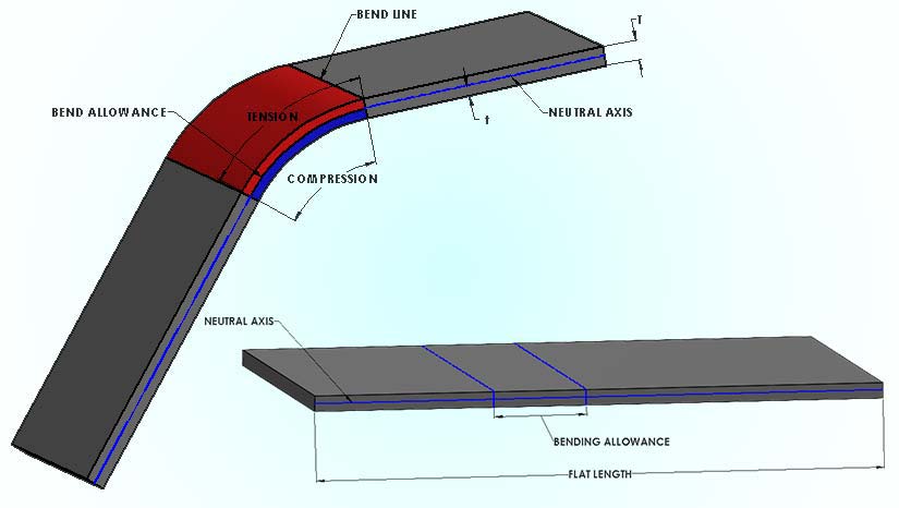
Accurately calculating bend allowance is vital when drafting sheet metal components, as even small errors can compound into significant dimensional problems during fabrication.
While drafting, designers must account for material thickness, bend radius and K-factor to determine precise bend deductions and guarantee manufacturability. The default internal bend radius of 0.030 inches (0.762 mm) serves as a starting point for many sheet metal designs, though this may vary based on specific material requirements.
The calculation process requires careful consideration of multiple variables that affect metal behavior during bending operations. Engineers must first determine the neutral axis location, which varies based on material properties and tooling specifications, and then apply appropriate formulas to compute the developed length.
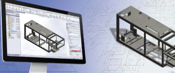
Modern CAD software, such as SolidWorks or Autodesk Inventor, helps automate many of these calculations, but understanding the underlying principles remains essential for maintaining sheet metal design accuracy.
Streamline your designs with detailed 2D sheet metal drawings.
Get accurate BOMs and flat pattern layouts tailored for your project.
Clearly include hardware specifications in sheet metal drawings
Hardware documentation in sheet metal drafting requires precise specifications to guarantee proper component selection and installation. Create standardized tables listing common hardware specifications, including material requirements, thread details, and installation parameters. Design for Manufacturability implementation ensures consistent hardware specifications across all drawings.
Develop hardware libraries containing pre-validated components with complete material specifications, including grade, finish, and compliance standards. Document mechanical properties, such as tensile strength, hardness, and corrosion resistance ratings in component datasheets.
Implement a structured naming convention for hardware components:
[Material]-[Type]-[Size]-[Thread]-[Finish]
For example: SS316-BHCS-M6-1.0-EP (Stainless Steel 316, Button Head Cap Screw, M6 diameter, 1.0mm pitch, Electropolished)
Critical hardware documentation elements include:
- Thread specifications (size, pitch, class)
- Material certifications and test reports
- Torque requirements
- Installation sequence
- Surface treatment requirements
- Quality control checkpoints
Maintain a hardware matrix showing compatibility between different materials to prevent galvanic corrosion. The following is an example:
| Base Material | Compatible Fastener Materials |
|---|---|
| Aluminum | SS300, SS400, Titanium |
| Steel | Zinc-plated, SS400 |
| Stainless | SS300, SS400, Inconel |
Carefully document special installation requirements like thread-locking compounds, anti-seize materials, and specialized tools. Create inspection checklists for quality control verification of hardware installations, including torque values, thread engagement, and material certification checks.
50% reduction in design iterations for sheet metal parts
An Irish designer, manufacturer, and installer specializing in recycling and material waste handling equipment sought to enhance their design process. The client required efficient and accurate design solutions for complex structures such as walkways, support structures, and hoppers, where minor changes in conveyor locations necessitated significant design rework.
HitechDigital implemented a top-down parametric design approach using Creo to address these challenges. This methodology allowed for the creation of adaptable master models, enabling seamless updates across all associated components when modifications occurred. The integration of this approach reduced design iterations by 50% and decreased design drafting time from 15-16 hours to 8-9 hours per hopper.
The final deliverables led to:
- 50% reduction in design iterations
- Design drafting time reduced from 15-16 hours to 8-9 hours per hopper
- Enhanced project efficiencies
Carefully consider material grain direction during sheet metal drafting
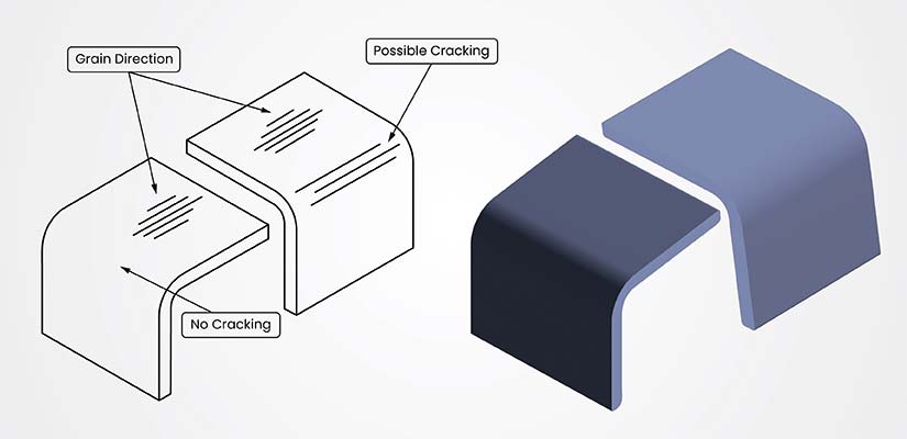
Document the grain direction requirements using standardized symbols, typically an arrow with “GD” notation, directly on the part drawings. Position these indicators prominently near the title block or within the Part Notes section.
Material thickness validation is crucial when determining grain direction to ensure proper bend allowances and to prevent material failure. Bending across grains produces stronger results with reduced cracking risks. Maintaining a consistent bend radius throughout the part helps to achieve uniform grain flow during forming operations.
For parts with multiple bends, analyze the most critical forming operations, and prioritize grain direction accordingly. When conflicting bend requirements exist, consider splitting the part into separate components or redesigning it to accommodate ideal grain orientation.
You can incorporate grain direction early in the CAD phase by:
- Setting up custom layer structures for grain direction visualization
- Using color coding to distinguish different grain orientations
- Adding grain direction arrows to flat patterns
- Including grain-specific bend notes
When specifying tolerances, account for material behavior variations based on grain direction. Specify tighter tolerances across grain, relaxed tolerances along grain, and additional spring-back compensation for bends parallel to grain.
Mark critical surfaces where grain direction affects functionality or appearance. For aesthetic components, specify grain direction to guarantee a consistent surface finish and visual alignment across assembled parts.

Download Essential Checklist to use CAD Software Efficiently
Be extra careful about documenting sheet metal dimensions and tolerances
In sheet metal drafting, precise dimensioning and tolerance planning require systematic consideration of manufacturing constraints and assembly requirements. Specific dimensions must account for material properties, forming limitations and stackup tolerances.
The following are the key dimensions that you need to specify:
- Flat pattern dimensions before forming
- Formed dimensions after bending
- Overall assembly envelope dimensions
- Critical interface points with mating parts
Dimensional relationships must be clearly defined through chain dimensioning for sequential features, baseline dimensioning from datum surfaces, true position callouts for critical holes, and profile tolerancing for formed surfaces.
When planning tolerances, consider material thickness variations, spring-back effects in forming, thermal expansion during welding, tool-wear impact on features, and assembly sequence requirements.
For tolerance allocation, follow these guidelines:
- Tighter tolerances for critical mating surfaces (±0.1mm)
- Standard tolerances for non-critical features (±0.5mm)
- Wider tolerances for formed features (±1.0mm)
- Specific angular tolerances for bends (±1°)
Implement tolerance zones based on feature accessibility and inspection methods. Use statistical tolerance analysis for complex assemblies with multiple sheet metal components to guarantee manufacturability and proper fit.
A comprehensive tolerance setting workflow in CAD software helps prevent costly production errors. Feature control frames standardize geometric tolerancing notations for enhanced communication between design and manufacturing teams.
Adhere to Design for Manufacturing (DFM) guidelines
Focusing on Design for Manufacturing (DFM) guidelines is crucial to ensure cost-effective manufacturability, reduce errors and rework, and improve the overall quality and efficiency of the final product.
Incorporate draft angles of 2-3 degrees on formed features to facilitate part removal from tooling. Position bend lines perpendicular to the grain direction of the material to prevent cracking and guarantee peak strength. Sharp edges are best protected using proper hem features to enhance safety and improve part rigidity.
Maintaining a distance of 1.5 T plus a bend radius between holes and bends prevents unwanted deformation during manufacturing. Welding locations should maintain uniform wall thickness throughout connected sections for optimal joint strength.
The following are some of the critical manufacturing parameters:
| Feature | Recommended Value |
|---|---|
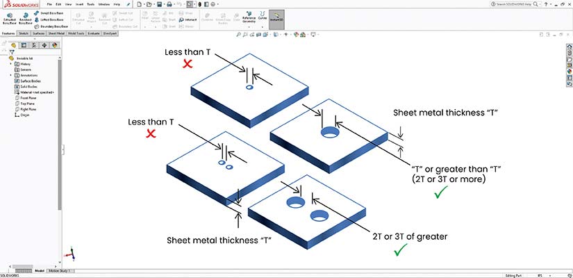
| Min. flange height | 4x Material Thickness |
| Min. hole diameter | 1x Material Thickness |
| Max. depth of draw | 2x Diameter |
| Min. emboss height | 0.8x Material Thickness |
Incorporate dimples and embosses for assembly alignment rather than complex positioning features. For formed flanges, maintain a minimum height of four times the material thickness to guarantee stability and prevent distortion.
Design self-fixturing features where possible to reduce assembly time and improve accuracy. Position holes and slots away from bends to prevent deformation during forming operations. When designing overlapping joints, account for material thickness to guarantee proper fit.
Here are some additional tips to remember for cost-effective production:
- Design parts with standard tools and equipment
- Use common material gauges and stock sizes
- Minimize the number of operations required
- Consider nesting efficiency for material utilization
Streamlining steel structure design for faster fabrication

A leading North American designer and manufacturer of open-air steel structures aimed to enhance their design efficiency. The client required over 1,800 manufacturing drawings and 3D models for various shelter structures, seeking to reduce engineering turnaround time (TAT) and improve design accuracy.
HitechDigital assembled a team of expert SolidWorks engineers with extensive knowledge of metal fabrication to develop manufacturing drawings and other documents for a range of different shelter structures. The team utilized SolidWorks 2019, employing a top-down design approach to facilitate quick design reviews and efficient change management. This methodology ensured accurate placement of features such as holes and hardware details, streamlining the fabrication process.
The final deliverables led to:
- 25% reduction in engineering turnaround time
- 50% decrease in design drafting iterations
- 100% first-time-right designs
Implement version control and change management for sheet metal drafting
Implementing robust version control and change management for sheet metal drafting guarantees accuracy, traceability and efficient collaboration. Each drawing revision requires clear identification through sequential numbering (Rev A, B, C) or date-based versioning (YYYYMMDD). Critical changes must be highlighted using revision clouds and triangular markers, with corresponding entries in the revision block.
Any change implementation follows the following step-wise structured workflow:
Step 1: Submit Engineering Change Request (ECR)
Step 2: Technical review of impact on manufacturability
Step 3: Cost and timeline assessment
Step 4: Stakeholder approval
Step 5: Implementation and documentation
Step 6: Drawing release with new revision
Branch management allows for the parallel development of design variations while maintaining the integrity of base documentation. Create separate branches for production releases, engineering trials, customer-specific modifications, and manufacturing optimization.
Sheet metal drawings should be managed in a centralized repository with strictly controlled access levels. The following table represents an example of access level against role/department
| Access Level | Role / Department |
|---|---|
| View only | Shop floor, procurement |
| Edit rights | Design engineers, drafters |
| Approval rights | Project leads, QC |
Implement automated backup systems that archive drawings daily, with full version history maintained for at least five years. Configure CAD software to autosave every 15 minutes and maintain local copies of working files. Regular audits should verify drawing accuracy, revision consistency, and the proper implementation of change management protocols.
Wrapping up
To achieve optimal manufacturing outcomes and avoid costly errors during fabrication, prioritize the implementation of best practices in your sheet metal drafting process. Standardized approaches to dimensioning, bend allowance calculations, draft angles, and feature documentation are crucial for consistent, high-quality production.
Adhering to the seven critical guidelines for sheet metal design discussed here, while leveraging modern CAD software features for drafting, will help you create precise, manufacturable drawings. These drawings will meet industry specifications and streamline your fabrication process, ensuring efficiency and accuracy in production.
Guarantee quality with international standards-compliant designs.
Validate designs with ANSI, IS, and TEMA certified professionals.