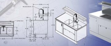

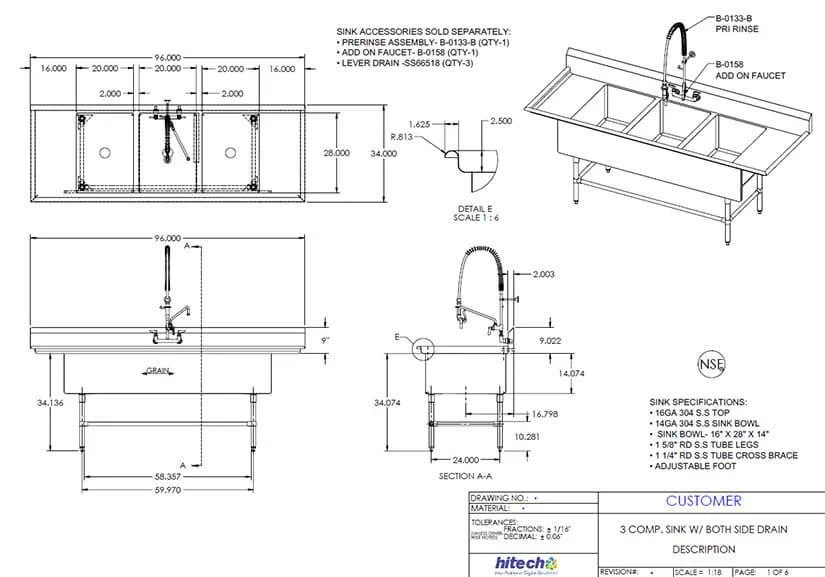
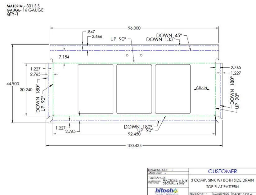
- Shop drawings relayed to metal fabrication shops communicate detailed product-specific design communication.
- These guidelines for transforming metal sheets into usable products include product geometry, instructions for operations such as joining, cutting, bending, and shearing among others.
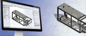
- Use of parametric 2D and 3D specialized CAD tools enhances the accuracy of these drawings.
Sheet metal shop drawings are blueprints for metal fabricators that play a central role in aligning the shop floor operations with the design intent. Detailed shop drawings not only streamline the fabrication process but also mitigate costly errors, delays, and reworks and ensure that every piece fits seamlessly into the larger assembly.
As demand for customization and more intricate work grows, the need for accurate sheet metal shop drawings becomes critical. For example, in kitchen cabinet manufacturing, shop drawings form the foundation for high-quality cabinets with no alcoves on completion. Amid this whole process, parametric CAD software controls the accuracy in detailing the drawings for designers, manufacturers, and installers.
Table of Contents
The Basics of Sheet Metal Shop Drawings
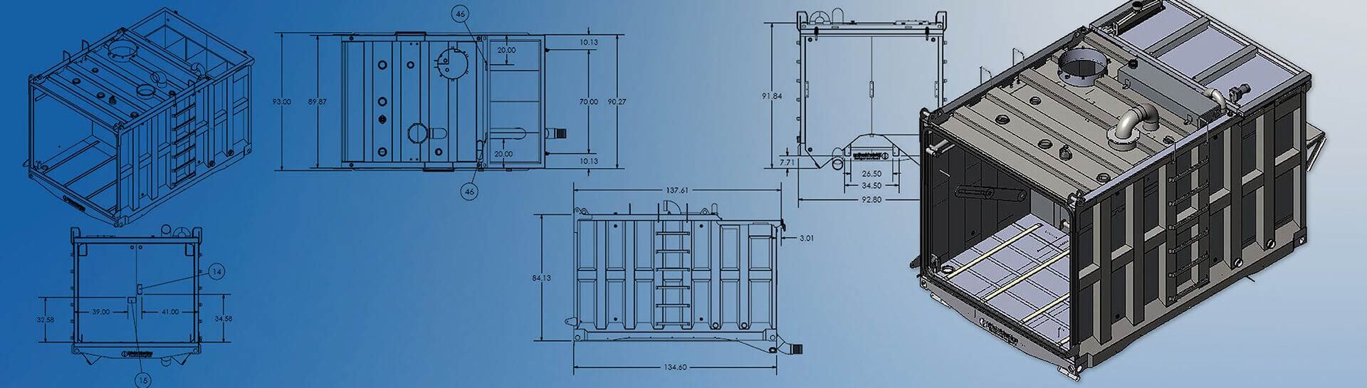
Sheet metal shop drawings are detailed technical drawings that provide instructions and information for the fabrication and assembly of sheet metal components. These drawings are typically created by engineers or draftspersons and used by sheet metal fabricators to produce accurate and precise products.
Accuracy in sheet metal drawings is paramount as it directly impacts the quality, fit, and functionality of fabricated components. Precise dimensions, tolerances, and material specifications ensure that parts align correctly, preventing costly errors in manufacturing. With accurate drawings, the fabricator or machine operator can punch in holes accurately, thereby ensuring structural integrity and safety.
8 Essential Elements in Design and Fabrication for Sheet Metal Shop Drawings
1. Detailed Dimensions
Clear dimension labeling serves as a universal language between designers and fabricators, reducing the risk of misinterpretation and errors. These dimensions must encompass critical parameters like length, width, and depth, leaving no room for ambiguity in the specifications. Tolerances, meticulously defined within the drawings, are vital for ensuring that every component fits precisely and functions flawlessly.
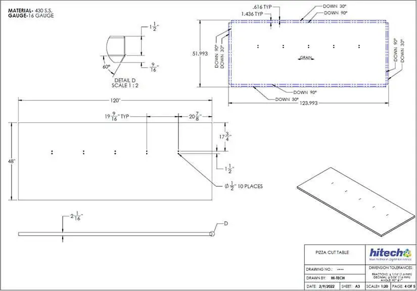
Specifying radius information for bends is equally crucial as it precisely guides the bending process, thereby preventing structural weaknesses and ensuring that sheet metal components conform to the original design intent. In sum, the detailing of sheet metal shop drawings hinges on these foundational principles to bring clarity and accuracy, ultimately delivering a successful fabrication outcome.
“Dimensioning and tolerances are your friend. By specifying tolerances for each dimension, you’re setting clear expectations and ensuring that the part meets the required specifications.”
– Nimesh Soni, Manager, Engineering Services & Solutions, HitechDigitalTips for detailing dimensions using CAD platforms:
- Use model dimensions: Whenever possible, use model dimensions. SolidWorks allows you to link drawing dimensions directly to model dimensions. This ensures that the drawing reflects any changes made to the 3D model.
- Smart dimension tool: SolidWorks provides a Smart Dimension tool that automatically recognizes and suggests dimensions as you select edges and features. This can significantly speed up dimensioning.
- Add reference dimensions: Besides critical dimensions, include reference dimensions that provide context and aid in understanding the design. These can help fabricators and inspectors.
- Apply geometric tolerances: Use Geometric Tolerance feature to specify tolerances for form, orientation, location, and profile. This helps communicate tolerance requirements more effectively.
- Organize dimensions: Group and arrange dimensions logically on the drawing to reduce clutter and improve readability. SolidWorks offers dimensioning standards that can help with this.
- Dimension to centerlines: For symmetric features, dimension to centerlines rather than edges. This ensures that the part is fabricated symmetrically, and it simplifies the drawing.
- Use baseline and ordinate dimensions: For multiple instances of the same feature, consider using baseline or ordinate dimensions to save space and make the drawing cleaner.
- Dimension patterns and arrays: When working with patterns or arrays of features, SolidWorks allows you to dimension one instance and then link the dimensions to the pattern. This saves time and maintains consistency.
- Employ dual dimensions: Dual dimensions (e.g., inches and millimeters) can be added to cater to both metric and imperial measurement systems, especially for international projects.
- Use custom symbols and notes: Create custom symbols or notes for special dimensioning requirements or additional information not covered by standard dimensioning tools.
- Apply model items: SolidWorks has a “Model Items” feature that can automatically import dimensions, tolerances, and annotations from the 3D model into the drawing.
- Update linked dimensions: If the 3D model changes, be sure to update the linked dimensions in the drawing to maintain accuracy.
Simplify your sheet metal drawing updates.
Unlock the power of parametric CAD platforms for sheet metal fabrication detailing.
2. Material Specifications
Selecting the right type of metal sheet is foundational, as it directly influences the component’s structural integrity, durability, and performance. Material thickness and grade are equally critical, as they dictate the sheet metal’s ability to withstand mechanical stresses and environmental conditions.
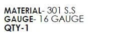
Designer must specify and highlight all special material treatments or finishes, such as coatings or heat treatments. This is necessary to achieve the desired aesthetic and functional qualities of the final product. Special attention to material empowers fabricators to choose, process, and treat sheet metal in a manner that helps achieve the intended outcomes.
Tips for material specification in the CAD environment:
- Use material libraries: Many CAD software applications offer material libraries that contain a wide range of pre-defined materials with associated properties. Take advantage of these libraries to save time and ensure consistency.
- Specify material properties: Clearly define material properties such as density, thermal conductivity, and mechanical properties like tensile strength, yield strength, and modulus of elasticity. This information is crucial for simulations and analysis.
- Custom materials: If your project requires a material not found in the standard libraries, create custom materials with the exact properties and characteristics needed. Ensure that these custom materials are well documented.
- Document material standards: Specify material standards or industry specifications (e.g., ASTM, ISO) to ensure that the material meets recognized quality and performance criteria.
- Material callouts: Clearly label materials on your drawings with standardized symbols and callouts. Include material names, grades, and any relevant codes.
- Include material thickness: When working with sheet metal or other materials with variable thicknesses, specify the thickness for each component. Highlight variations if they exist.
- Color coding: In some CAD software, you can color-code parts or components to represent different materials visually. This can be helpful for quick identification.
- Attach material datasheets: Attach datasheets or documents detailing material properties, manufacturer information, and any special handling or fabrication instructions as reference material within the CAD file.
- Use material tags: Use material tags or annotations to add notes about specific material requirements, treatments, or finishing, directly onto the CAD drawing.
- Update material information: If there are changes to material specifications during the design process, CAD models should be updated too. All instances of material change must be reflected in CAD files to maintain consistency.
- Version control: Implement version control for your CAD files to track changes to material specifications. This helps avoid confusion and ensures that everyone is working with the latest information.
- Document material alternatives: If there are acceptable alternative materials that can be used, document these options in shop drawings. Also, mention the pros and cons of the design review process.
3. Bend Information
Understanding the intent for bend angles and directions is the key to accuracy. It defines how the material will deform during bending, ensuring that the finished part matches the intended shape. Equally important is grasping the concept of bend allowances or k-factors to account for material stretch and compression during bending. This guides fabricators to calculate the correct bend deductions and make the cuts accordingly.
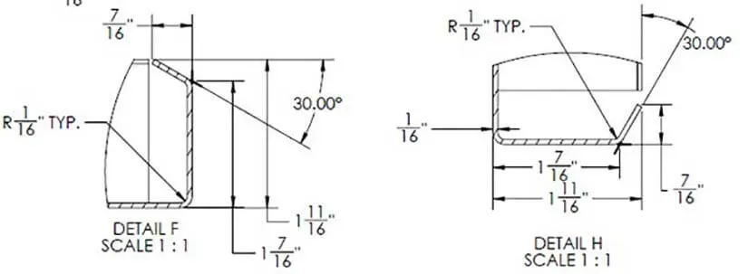
Within this framework, highlighting critical bends is essential. It distinguishes bends that must adhere to tight tolerances or those that significantly impact the part’s structural integrity or functionality.
“Usually standard value of K-factor is 0.5, but it has to be modified based on several factors like machines used. Talk to your sheet metal design engineer gives advises to modify this value and ensure seamless fabrication.”
– Nimesh Soni, Manager, Engineering Services & Solutions, HitechDigitalTips to calculate bend deduction in CAD software:
- Create sheet metal part: Start by creating or importing your 3D sheet metal model in SolidWorks.
- Define material and thickness: Ensure that you have defined the correct material and thickness for your sheet metal part. This information is crucial for calculating the bend deduction accurately.
- Add bends: Use the “Insert Bends” feature in the Sheet Metal toolbar to add bends to your model. You can select edges or sketch lines that represent the bend lines. SolidWorks will automatically create bend features.
- Access the bend deduction value: After adding bends, you can find the bend deduction value in the feature tree. It’s listed under the “Bend Deduction” column in the “Sheet-Metal1” folder (or a similar name, depending on your feature tree structure).
- Use the bend deduction value: The bend deduction value provided in SolidWorks is typically used in the flat pattern development of the sheet metal part. It helps calculate the correct flat pattern size by accounting for the material’s stretching and compressing during bending.
- Modify bend deduction: If needed, you can manually adjust the bend deduction value in the Sheet Metal feature’s property manager. This can be useful when working with non-standard materials or when specific manufacturing practices are applied.
Achieve precision in your product bends.
Leverage an extensive range of CAD features to detail your sheet metal drawings.
4. Hole and Cutout Details
Precision in marking the location, size, and shape of hole openings ensures that the sheet metal components will assemble accurately. Perfecting these features guarantees functionality and fit of the assembly as intended.
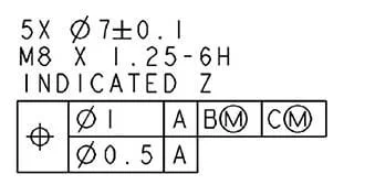
Special requirements for hole edges are critical considerations. These may include specifications for deburring, chamfering, or adding specific edge treatments for safety and prevention of sharp edges. Paying attention to holes and cuts on sheet metal also helps focus maintaining the structural integrity of the part.
In the case of cutting metal sheets, the workpiece undergoes a specific set of operations. This usually starts with shearing, followed by punching, and finally laser cutting.
“A common mistake we see in drawings is unclear hole locations. Always double-check that the size, location, and tolerance of holes are clearly indicated. This is vital for parts that need to be assembled with fasteners.”
– Nimesh Soni, Manager, Engineering Services & Solutions, HitechDigitalTips to detail holes and cutout details in the CAD platform:
- Sketching geometry: Start by creating a sketch that represents the geometry of the hole or cutout on the right plane of your 3D sheet metal model.
- Dimensioning: Use dimensioning tools to specify the size and location of the hole or cutout. You can typically dimension the center point, diameter, or width, and any relevant distances from reference points or edges.
- Hole feature: Many CAD tools have specific hole feature tools. You can select the sketch, choose the hole type (e.g., counterbore, countersink, simple hole), and define parameters such as depth and thread specifications.
- Cutout feature : For non-hole cutouts, such as irregular shapes or openings, use the cutout or extrude-cut feature. Select the sketch representing the cutout shape, specify the depth, and apply the cut operation to the sheet metal part.
- Annotations: Use annotation tools, such as notes, symbols, or balloons to provide additional information or callouts regarding the hole or cutout. These annotations can convey details like thread type, tolerance, or any special requirements for the hole or cutout.
- Edge treatments: If there are specific requirements for the edges of the hole or cutout (e.g., chamfer, fillet, deburring), be sure to include these details in your annotations using CAD tools.
- Layer management: Organize your hole and cutout details on different layers or in separate drawing views to improve the clarity and readability of your sheet metal drawing.
- Hole tables: Some CAD software packages offer hole table functionalities. These tables can automatically list and detail multiple holes in a clear and structured format, including information such as quantity, size, and spacing.
- 3D Modeling: 3D CAD models offer a comprehensive view of holes and cutouts positions and relationships within the sheet metal component.
- Dimension Styles: Customize dimension styles to match your sheet metal drawing standards, and make sure the dimensions are clear and easy to read.
5. Welding and Joining Instructions
Choices between welded and screwed joints are crucial to ensure functional stability of the parts being joined. While welding can be a robust method, it often comes at a higher cost because of the need for specialized skills and equipment. Screwed joints or fasteners are relatively simpler to implement and may be preferred in certain situations. Detailing types of welds, such as fillets, grooves or spot welds, and their specific applications is essential.
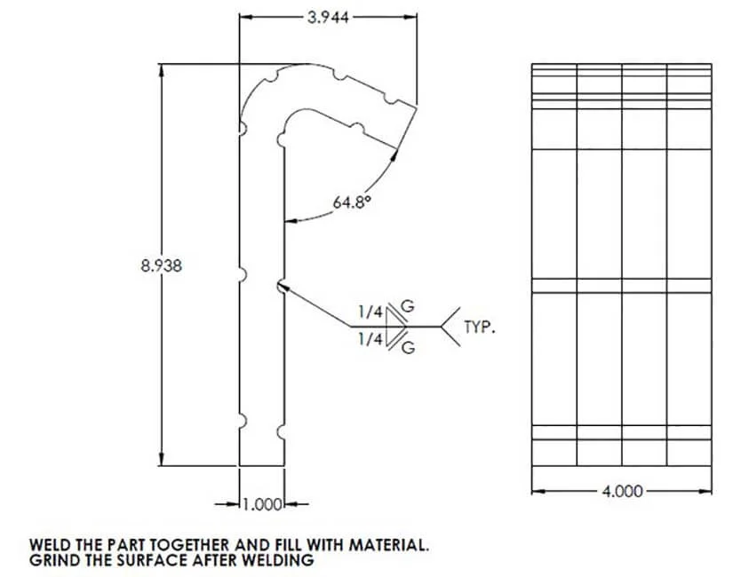
Precisely specifying weld size and location ensures that the welding process adheres to design standards, maintaining the part’s integrity. Including special instructions for the welder, such as welding techniques, pre-heat or post-weld treatments, and quality control measures, is imperative to welding process. Aligning these factors with the design intent and quality standards essentially guarantees weld quality.
In essence, welding and joining instructions are the cornerstone of translating design concepts into dependable and structurally sound sheet metal products.
“Different sheet metal fabrication projects require specific welding techniques, such as TIG or MIG welding. And welding instructions are our roadmap, ensuring that each component fits together seamlessly to create the final product.”
– Nimesh Soni, Manager, Engineering Services & Solutions, HitechDigitalTips to specify welding and joining instruction in CAD environment:
- Clear annotation: Use text annotations and labels in your CAD drawings to clearly specify welding and joining details. Include information such as the type of joint, welding method, and any special instructions for assembly.
- Weld symbols: Use welding symbols and their associated meanings as per welding standards (e.g., AWS and ISO). CAD software often provides a library of standard welding symbols you can insert into drawings.
- Joint types: Clearly define the type of joint, whether it’s a butt joint, lap joint, fillet weld, groove weld, or any other specific configuration. This information guides the fabricator in understanding how the parts should be joined.
- Weld size: Specify the weld size accurately, including the dimensions for fillet weld leg length or groove weld depth and width. Ensure that these dimensions are as per design requirements and welding codes.
- Welding process: Show the welding process to be used, such as MIG, TIG, or spot welding, in the drawings. Include any specific settings or parameters relevant to the chosen process.
- Weld location: Clearly mark the exact location where the weld is to be applied. Use dimensions, reference points, or coordinate systems to pinpoint the weld’s position accurately.
- Welding sequence: If multiple welds are involved, provide a welding sequence or order of assembly. This will prevent interference or misalignment issues during and after the welding process.
- Weld preparations: Specify any required weld preparations, such as beveling or chamfering of edges before welding. This ensures proper joint fit-up.
- Welding symbol legend: Include a legend or key in your drawing that explains the meaning of all welding symbols and notations used in the drawing.
- Surface preparation: If specific surface treatments or preparations are necessary before welding (e.g., cleaning, rust removal), provide clear instructions for these steps.
- Quality control requirements: Detail any quality control measures, inspections, or testing procedures that need to be followed during or after welding.
- Special instructions: Include any special instructions or notes for the welder, such as welding rod or wire type, welding sequence, and any post-weld heat treatment requirements.
- Material compatibility: Ensure that the welding method and filler materials specified are compatible with the base material and meet the project’s requirements.
- Collaboration: Collaborate closely with welding experts and fabricators to strictly follow the industry best practices while detailing drawings for welding. This will work towards increased efficiency and capabilities of your welding team.
Why wait to create robust sheet metal products?
Take the first step towards exceptional craftsmanship.
6. Hardware and Assembly Details
To ensure that components come together perfectly in a multi-component sheet metal assembly, shop drawings need specs of all hardware. This involves listing all components—from fasteners like screws, nuts, and bolts to specialized components such as hinges or latches. Each hardware item must be accurately identified for showing the quantity.
It is equally important to provide clear assembly instructions to guide fabricators or assemblers step by step. It should include the type of hardware, their precise locations, torque or fastening specifications, and any special techniques or tools required. By meticulously detailing hardware assembly in this manner, shop drawings become an indispensable tool for ensuring that the final product is not only structurally sound, but also assembled correctly and efficiently.
Tips to add sheet metal hardware details in CAD:
- Create a hardware list: Compile a comprehensive list of all hardware components required for assembly. This list should include items such as screws, bolts, nuts, washers, rivets, fasteners, hinges, handles, and any other relevant hardware.
- Use standard symbols: Use standardized symbols and notations for hardware components. CAD software often provides a library of common symbols for various types of hardware, making it easier to communicate the intended components.
- Include hardware callouts: Place callouts or labels near the areas where hardware components are to be installed. Use clear text and symbols to show the type, size, and quantity of each component.
- Detail hardware locations: Clearly specify the exact locations where each hardware component is to be installed on the sheet metal part. Use dimensions, reference points, or coordinates to pinpoint these locations accurately.
- Specify hardware types and grades: Specify the type and grade of hardware components. For example, show if a hinge of the door or the lock should be stainless steel. Also specify thread types, and provide information about any special coatings or treatments.
- Thread details: For threaded hardware like screws and bolts, include thread specifications, such as thread pitch and thread depth. This ensures compatibility and proper engagement.
- Fastening instructions: Provide clear instructions on how each piece of hardware should be fastened, including torque values, if applicable. Specify any required tools or equipment.
- Clearances and tolerances: Specify any necessary clearances and tolerances around hardware components to ensure proper fit and functionality. Consider factors like thermal expansion and manufacturing tolerances.
- Hardware legends: Create a legend or key within the drawing to explain the meaning of symbols, abbreviations, and codes used for hardware. It will avoid confusion while collaborating with cross functional teams.
- Hardware schedule: Include a hardware schedule/table that summarizes all hardware components, their quantities, sizes, and locations in one place for easy reference.
7. Revision History
Revision tracking and history documentation offer reliable records of all modifications in drawings across the design and fabrication process. To mark and track the latest revisions effectively, it’s essential to use a systematic approach. This can be established by clearly labeling each revision with a unique identifier or date.
By doing so, both designers and fabricators can access the latest drawing version with a history of changes. This will be helpful particularly during audits and quality checks. It will also reduce the risk of errors and enhance the overall efficiency and reliability of the sheet metal fabrication process.
“A good practice we’ve adopted in our shop is to always review the revision history before starting on a new project or making changes to an existing one. It helps us understand the evolution of the design and ensures that we’re working from the most up-to-date information.”
– Nimesh Soni, Manager, Engineering Services & Solutions, HitechDigitalTips for revision history and control in CAD environment:
- Version control: Implement a version control system that assigns unique identifiers or revision numbers to each iteration of the drawing.
- Date and author stamps: Clearly mark each revision with the date it was made and the name or initials of the person who made the changes. This helps identify when and by whom each revision was made.
- Revision clouds: CAD software often provides revision cloud tools that allow you to draw clouds around areas that have been changed. These clouds make it easy to visually spot changes.
- Revision tables: Consider adding a revision table to your drawing sheet. This table summarizes the revision history, including revision numbers, dates, and descriptions of changes made. Some CAD software can automate this table.
- Color coding: Use color coding to differentiate between old and new elements in the drawing. Highlight newly added or changed features with a distinct color to make them stand out.
- Layer management: Organize your drawing layers to separate current and past revisions. You can toggle the visibility of layers to easily switch between revisions for reference or comparison.
- File naming convention: Establish a consistent file naming convention that includes the revision number or date. This makes it easy to identify the latest version of a drawing from its file name.
- Digital signatures: In some cases, digital signatures or metadata can be added to CAD files. It certifies the authenticity of the drawing and the person responsible for the revision.
- Comments and markups: Use CAD software’s comment and markup tools to annotate and describe changes made in each revision. These annotations can provide context and clarification.
- Backup and archive: Regularly back up and archive previous versions of the drawing files. This ensures that historical revisions are securely stored and easily retrievable, if needed.
- Real-time collaborative platforms: If multiple CAD users are working on the same drawing, use platforms with real-time collaboration features to easily track changes.
- Regular reviews: Schedule regular drawing reviews with team members to ensure that everyone is aware of and understands the latest revisions. Address any concerns during these meetings.
- Documentation control: Maintain a document control system that includes logs of revisions, reasons for changes, and approvals. This provides a comprehensive record of the drawing’s history.
Take full control of design-to-fabrication journey
Maintain a digital log of CAD drawings for easy document retracing.
8. Feedback Loop with Fabrication Team
Firsthand information and insights from the fabrication team are invaluable to the CAD design teams. They help identify potential design improvements, optimize manufacturing processes, and resolve any practical challenges that may arise during fabrication. But it’s crucial to establish a systematic approach for continuous feedback and improvement.
Creating an open channel of communication where sheet metal fabricators can provide input, report issues, and suggest modifications is critical. Regular meetings or check-ins can be scheduled to review feedback and implement necessary changes, fostering collaboration between design and fabrication teams. This iterative feedback loop not only enhances the quality and efficiency of the fabrication process, but also infuses continuous improvement.
Tips to have an effective feedback loop with CAD:
- Collaborative CAD software: Use collaborative CAD software or tools that allow multiple team members to work on the same drawing simultaneously. This enables real-time feedback and design adjustments.
- Redline markups: Fabricators can provide redline markups on CAD drawings to highlight areas of concern or areas where design modifications are needed. These markups can be scanned and incorporated into a digital CAD file.
- Version Control: Maintain version control for CAD files to keep track of revisions. Ensure that the most up-to-date version of the drawing is accessible to both the design and fabrication teams.
- Review and approval process: Implement a review and approval process for design changes. Both the design and fabrication teams should review and approve modifications before design is finalized.
- Quality assurance: After incorporating feedback and making design changes, be sure to conduct quality assurance checks. Run the checks only for modifications to ensure that no new issues are raised.
- Training and knowledge sharing: If recurring issues arise, consider organizing training sessions or knowledge-sharing activities between the design and fabrication teams to address specific challenges.
- Continuous improvement: Continuously monitor the impact of design changes on fabrication processes and product quality. Solicit ongoing feedback to drive continuous improvement in the design and fabrication workflow.
Leveraging CAD Software for Accurate Sheet Metal Detailing
Leveraging CAD software like SolidWorks and Autodesk Inventor is essential for achieving precise and efficient detailing in sheet metal designs. These tools offer specialized and rich features tailored to sheet metal fabrication design, allowing designers to create accurate 3D models, generate detailed shop drawings, and conduct simulations to assess structural integrity and fit. SolidWorks excels with its intuitive parametric modeling, while Autodesk Inventor’s robust assembly capabilities are ideal for facilitating complex sheet metal assemblies.
Both software options provide specialized tools for sheet metal-specific operations, such as bend deductions, flat pattern development, and automatic generation of production-ready drawings. Parametric CAD tools ensure that any design changes are cohesively reflected throughout the model and drawings, thereby enhancing design accuracy and streamlining communication between design and fabrication teams. The impact of these platforms ultimately leads to the production of high-quality, precisely fabricated sheet metal parts.
Conclusion
Detailing sheet metal shop drawings accurately is a fundamental necessity for fabricators to remain profitable. These detailed blueprints are the cornerstone of precise fabrication, applicable to kitchen cabinets, doors, window frames, and any other sheet metal component. Modern and parametric CAD platforms play a critical role in this process.
For fabricators striving to achieve standard quality and efficiency, investing in professional sheet metal CAD drafting services is not merely a choice, but a strategic necessity. By doing so, fabricators can build their projects on a foundation of precision, thereby reducing errors, streamlining production, and ultimately delivering superior sheet metal components. Successful collaboration between design and fabrication teams, with a focus on accuracy, remains the key to thriving in the ever-evolving landscape of sheet metal manufacturing.
Ready to elevate your sheet metal fabrication?
Let’s collaborate to create extraordinary metal products!