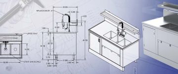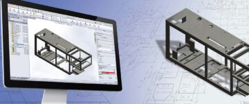

- In any fabrication shop, sheet metal CAD drawings are the single source of truth. They’re the blueprint that dictates every step from design validation to the final assembly.
- Our workflow relies on several key types: part drawings, flat patterns, shop drawings, assembly drawings, multiple views and development drawings. Each serves a specific and important function.
- Getting these accurate sheet metal fabrication drawings right from the start is what makes sure we get dimensional accuracy, stops unnecessary material waste and ends the costly back and forth between the design office and the production team.
Table of Contents
Fabricators burn time and money when the sheet metal drawings they get are unclear. From our experience, an unspecified dimension or a missing tolerance forces guesswork on the shop floor. That guesswork is the number 1 cause of scrapped parts, expensive rework and production delays that can kill a project’s profitability.
The only way to combat this is to use a specific, comprehensive set of sheet metal CAD drawings that is the unambiguous blueprint for each fabrication step.
The different drawing types work together to tell the full manufacturing story. Part drawings are laser focused on the specifications for individual components after they’ve been formed. Flat pattern drawings are a completely different tool, providing the unfolded 2D geometry needed to program the cutting machines.
Shop drawings act as the practical, hands on script for the fabrication and welding teams. Then assembly drawings show how all the finished parts are supposed to fit together, and development drawings are for the more complex task of turning a flat sheet into a formed 3D shape.
This structured documentation package covers the entire fabrication process—from a raw sheet of aluminum to the final assembled product—and it eliminates ambiguity.
The real value is how it slashes the need for costly iterations and accelerates the production timeline. All while making sure the final product meets all quality and compliance standards.
What are sheet metal CAD drawings?
At their core, sheet metal CAD drawings are technical plans generated from digital models. In practice, they provide direct, actionable instructions for all the cutting, bending, hole placement and finishing operations in sheet metal fabrication.
A good drawing must contain all important information—material type, gauge, bend angles and the crucial K-factors. All of this is annotated with industry standard tolerances.
A complete 2D sheet metal drawings package usually includes multiple views—most commonly the flat patterns, formed views from various angles and specific section details. When we look at them together, these different perspectives help everyone on the team, from the press brake operator to the quality inspector, better understand the geometry and requirements of the finished part.
Before any drawing is released to the floor, it’s rigorously reviewed by both engineers and the fabricators themselves. This step is crucial for validating a part’s fit, function and manufacturability.
This process is what makes sure the physical parts will actually match the digital models and provides the necessary documentation for quality control.
Why accurate sheet metal CAD drawings matter
The quality of your sheet metal CAD drawings directly determines the efficiency and cost of the entire fabrication process. Without sheet metal drafting best practices, poorly made drawings can create downstream problems, while accurate ones help prevent them. Here’s a breakdown of the key impacts:
- Error prevention in manufacturing: In our experience, a good drawing that accounts for material properties and forming methods eliminates most dimensional deviations during cutting and bending.
- Optimizing your material and reducing waste: Properly designed sheet metal manufacturing drawings lets you efficiently nest parts. When parts are better fitted on a single sheet, this reduces scraps and has a direct effect in lowering material costs.
- When you are looking for accurate assembly, proper documentation of tolerances and bend allowances is what makes sure different components will fit together in complex assemblies.
- CNC integration and automation: In order to make your fabrication workflow smooth, you need direct integration with CNC. CAD drawings for sheet metal provide the digital data that is used for direct CNC programming.
- Quality control: Shop drawings are the absolute reference standards for all inspection activities, and this makes the process of quality checking a lot easier and efficient
- Clearer communication across teams: A clear and detailed drawing lets you convey the design very well to you manufacturing and quality teams. This creates a single source of truth for all the stakeholders.
- Standardization on the shop floor: Detailed drawings help you remove any scopes of guesswork during fabrication. This is very important to get consistent results across different production runs.
- Helps you to scale production: When you are dealing with high volume productions, you will need to frequently replicate components while maintaining the same quality. Accurate CAD drawings makes this easy by serving as a common blueprint.
Different types of sheet metal drawings used in fabrication
Sheet metal work requires different drawing formats. Each fabrication drawing type is designed while keeping in mind a specific need in the production workflow.
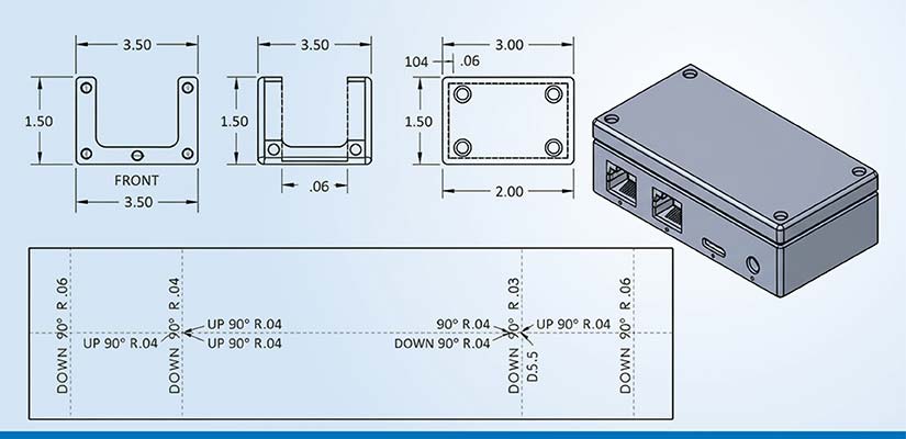
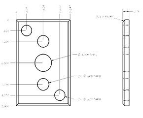
Part drawings for single components
Sheet metal part drawings are the main reference information for a single component. They detail its complete geometry and specifications for its final, formed state.
We use this drawing to understand the designer’s intent. This same drawing is also used to verify all dimensions after the manufacturing operations are complete.
The key elements that must be in a part drawing are broken down as follows:
Geometric definition
- It should have the primary dimensions for the overall part size.
- You’ll also need secondary dimensions for specific features relative to datum targets.
- All the interface surfaces should have clear tolerance callouts.
- Hole patterns should be defined with coordinates and diameter specifications.
Forming information
- Make sure that bend lines follow proper line type conventions for clarity.
- We’ve found that specifying the proper size and style of bend reliefs is important to prevent material tearing.
- Corner treatments like notches or chamfers are important for compatibility of different parts while assembling them.
- Any hemming or edge treatments should be detailed for both safety and structural reasons.
Material & process specifications
- The drawing should specify the material type, grade and thickness.
- Any surface treatment, like pre-galvanized or pre-finished, needs to be noted.
- Finishing notes for processes like painting or plating are also required.
- You must also include any special process requirements, such as hardware insertion or deburring.
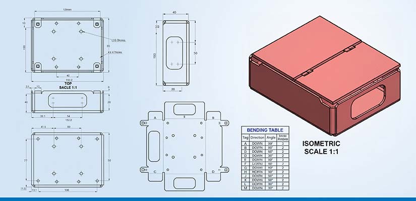
Flat pattern drawings for cutting operations
A flat pattern drawing shows a component completely unfolded. This isn’t a design document. It’s a manufacturing template we use specifically for programming CNC cutting machines like lasers or waterjets.
Essential elements in flat pattern drawings include:
- Manufacturing data: This covers material specs like grade and thickness, the preferred cutting method and any necessary kerf allowances.
- Precision elements: You’ll find bend lines with direction indicators, relief cuts at intersections and specific springback compensation values.
- Process integration: These drawings often have CAM ready annotations and inspection callouts linked to the quality system.
Say for example a flat pattern for a stainless-steel bracket will require a different overbend specification than one for softer aluminum to achieve the exact same final angle. Their springback characteristics are completely different.
Early collaboration with fabricators is crucial here because each cutting method has unique requirements. A turret punch operates with different tolerances than a laser system, just as high strength steels require more springback compensation than mild steels.
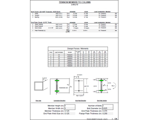
Shop drawings for fabrication and assembly
Sheet metal shop drawings are the comprehensive, all in one documents that contain all the manufacturing information needed for production on the shop floor. They act as the complete script for fabrication and installation.
The key components of sheet metal shop drawings are:
- Fabrication ready information: This means exact hardware specifications with part numbers, weld callouts with type and size and specific tooling notes for each step in the process.
- Production management elements: This includes revision tracking and cross references to quality inspection reports.
A complete shop drawing package will typically include PDF documentation for easy reference on the shop floor, as well as production ready DXF/DWG files that can be fed directly to the machines for programming.
The bend table details within these drawings are particularly important because they provide the specific forming information that guides the press brake operators.
Cut fabrication delays with DFM-aligned sheet metal CAD
Partner with CAD experts who know fabrication floors
Assembly drawings for multiple components
Assembly drawings illustrate how individual sheet metal parts are meant to fit together to create a final product or subassembly. Their primary purpose is to provide context.
Here’s a breakdown of the main elements in these drawings:
| Element type | Information provided | Fabrication value |
|---|---|---|
| Fastener specifications |
|
Ensures proper procurement and installation |
| Joining methods |
|
Guides permanent connection creation |
| Component identification |
|
Links to individual part drawings |
| Spatial relationships |
|
Prevents interference issues |
| Assembly sequence |
|
Facilitates efficient assembly |
Assembly drawings are used throughout the fabrication process, from guiding technicians during the build to helping quality inspectors verify the final product.
Development drawings for curved or complex shapes
Development drawings are a specialized type we use for the complex task of translating 3D curved surfaces into 2D flat patterns. This is essential for any component that can’t be made with simple bends.
A classic example is the \”square-to-round\” transition that’s incredibly common in HVAC ductwork. The drawing uses methods like radial line development for conical forms or triangulation for more irregular shapes to accurately map the geometry.
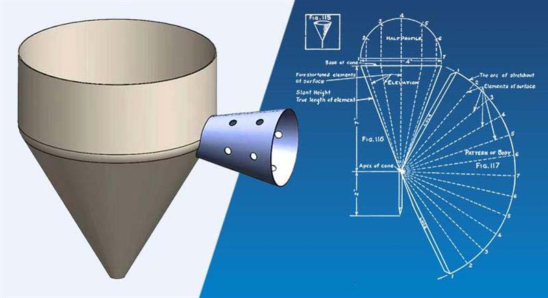
For example, a sheet metal funnel used in pharmaceutical equipment requires accurate development drawings to make sure there’s proper material flow. The truncated cone shape would use radial line development, with the flat pattern showing precise cut lines and allowances for welded seams.
The drawing must account for material thickness variations and have specific notations for forming accuracy, often as tight as ±0.2mm, to maintain consistent powder flow rates.
Without this level of detail, the fabricated funnel can develop an inconsistent curvature. This leads to product buildup and potential contamination issues.
Exploded and section view drawings
Exploded view drawings pull an assembly apart to show how the individual parts fit together and in what sequence. It’s an invaluable tool for planning an installation or for troubleshooting a complex build.
Section view drawings, on the other hand, provides a \”cutaway\” look inside a part or assembly. We use it to reveal internal features, joints and component relationships that are important for fabrication but would otherwise be completely hidden from view.
For complex sheet metal assemblies with many internal parts, section views are indispensable for clarifying the design.
We primarily use these drawing types for installation planning and troubleshooting, as they clearly show the assembly sequence and any potential internal interference points.
Key elements in sheet metal drawings for fabrication
To be effective, every sheet metal fabrication drawing must contain several key elements:
- Primary dimensions: This is the overall dimensions that define the part’s geometry.
- Tolerance specifications: You must include acceptable variation ranges that balance functional needs with manufacturing capabilities.
- Bend lines: This is the exact locations where the material will be formed, using standard line types for clarity.
- Bend angles and radii: The drawing needs to specify exact angular relationships and forming radii that match the available tooling.
- Bend allowance calculations: This is the material compensation factors needed to account for stretching or compression during forming.
- Material specifications: This includes the exact material type, grade, thickness and surface finish.
- Hardware details: Any fastener types, sizes and quantities for assembly parts must be listed.
- Weld symbols: The drawing must use standardized notation for joint types and sizes.
- Surface treatments: Finishing specifications for painting, plating or other post processing are also required.
When we document these elements correctly, they eliminate ambiguity and make sure the final fabricated parts meet both form and function.
Efficient delivery of 1,800+ shelter structure drawings
 Input – 3D Model
 Output – Manufacturing Drawings
 Input – Technical Calculation
 Output – Drawings after Model Verification
A North American designer of open air steel shelter structures was struggling with iterative design, detailing complexity and tight fabrication lead times. They needed verification of hole placements, hardware details and fabrication ready drawings for high volume structures.
HitechDigital used a top down approach in SolidWorks to deliver over 1,800 structural and manufacturing drawings. Our team of experts validated assembly, managed change cycles and made sure fabrication was uninterrupted through rigorous reviews and BOM enriched 2D documentation.
The results were:
- A 25% faster engineering turnaround
- 50% fewer design iterations
- 100% first time right designs
CAD tools used for sheet metal drawings
| Software | Sheet metal features | Flat pattern generation | Drawing automation | CNC integration |
|---|---|---|---|---|
| SOLIDWORKS | Full sheet metal environment with dedicated toolbar | Automatic development with bend compensation | Automated view creation and dimension tools | Direct export to major CAM systems |
| Autodesk Inventor | Robust sheet metal workbench with rule-based | Advanced unfolding with custom K-factor libraries | Drawing template automation and view inheritance | Integrated CAM and DXF/DWG export |
| Fusion 360 | Cloud-based sheet metal tools with collaboration | Real-time flat pattern development | Drawing automation with cloud sharing | Integrated CAM workflows |
| Autodesk AutoCAD | Limited sheet metal tools but flexible drafting | Manual flat pattern development | Limited automation for sheet metal | Standard DXF/DWG export |
| Creo | Parametric sheet metal design with simulation | Advanced development with multiple methods | Comprehensive drawing automation | Strong manufacturing integration |
Conclusion
Sheet metal CAD drawings are the essential bridge between a design concept and a successful fabrication run. Each drawing type has a distinct purpose, and together they create a complete manufacturing roadmap that eliminates guesswork and makes sure everyone is working from the same set of plans.
As fabrication technology continues to improve, the integration between CAD systems and automated equipment on the shop floor will only get tighter. For us fabricators, a relentless focus on drawing accuracy, completeness and clarity will always be the key to getting successful, profitable results.