

- Implementing quality metrics in sheet metal fabrication drawings is essential for ensuring product quality and reducing errors.
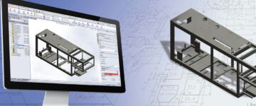
- CAD software helps to maintain precision and efficiency in quality assurance processes, leading to consistent and high-quality sheet metal outputs.
- Adhering to industry standards and using standardized symbols for welding and joining details ensures better fabrication quality and structural integrity.
Dimensional accuracy, tolerance specifications, material specifications, surface finish, and welding symbols are five key metrics in sheet metal fabrication drawings, important for high standard product quality. These metrics reduce errors and improve production efficiency. They serve as a guideline for quality assurance in design and manufacturing.
Table of Contents
- Quality Metric 1: Measuring Dimensional Accuracy
- Quality Metric 2: Measuring Material Specification Accuracy
- Quality Metric 3: Measuring the accuracy of Surface Finish and Texturing details
- Quality Metric 4: Measuring Tolerance Representation accuracy
- Quality Metric 5: Measuring Welding and Joining Details Accuracy
- Implementing and Monitoring Quality Metrics
- Role of CAD software in quality control and assurance
- Conclusion
A thorough understanding and implementation of quality metrics is essential at the drawing stage as they ensure that the end product in sheet metal fabrication meets the required specifications and performance standards.
The global market for Sheet Metal Fabrication Services, estimated at US $15.3 Billion in the previous year, is projected to reach $19.6 Billion by 2030, growing at a CAGR of 3.1%.
These metrics, when meticulously applied, streamline production workflows, minimize waste, and uphold the structural integrity of the final product.
In the following sections we have explored the top 5 key quality metrics in sheet metal fabrication drawings, providing insights on how they can be effectively implemented to enhance quality control and overall production success.
Quality Metric 1: Measuring Dimensional Accuracy
Dimensional accuracy ensures that the details in shop drawings match the specified dimensions in the design. Dimensional accuracy is vital for the fit, function, and assembly of the parts into larger systems.
The following are the key aspects of this quality metric:
- Tolerance Levels: Defined as the permissible limit of variation in a physical dimension. Tolerances are critical to ensure parts fit together correctly.
- Precision Measurement Tools: Use of calipers, micrometers, and Coordinate Measuring Machines (CMMs) for accurate measurement.
- CAD Software Accuracy: Ensuring the drawing and design software used (like SolidWorks or Inventor) is capable of producing precise dimensions.
- Fabrication Process Control: Techniques like laser cutting or CNC machining offer high precision, affecting dimensional accuracy.
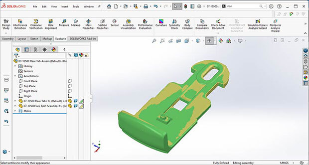 3D laser scanning of sheet metal component
Following Design for Manufacturing and Assembly (DFMA) guidelines are also crucial for ensuring the dimensional accuracy of sheet metal fabrication drawings. By adhering to these guidelines, engineers can create designs that are both functional and easy to manufacture.
CAD tools and techniques to ensure precise measurements
In sheet metal fabrication, CAD (Computer-Aided Design) tools ensure flexible and adaptive design changes by employing parametric modeling that allows designers to define dimensions with relationships between elements. This makes sure that any changes made to the design automatically update throughout the model, maintaining design intent.
CAD software includes snap-to-grid and geometric constraints functions that prevent errors during manual input. These also come with specialized features like automated dimensioning tools to generate accurate measurements directly within the drawing, saving time and reducing human error.
CAD applications such as Autodesk Fusion 360, offers specialized bend and unfold commands, sheet metal-specific parameters, corner reliefs, flange creation, and more. Such features streamline the design process, enabling the creation of complex sheet metal components with accuracy.
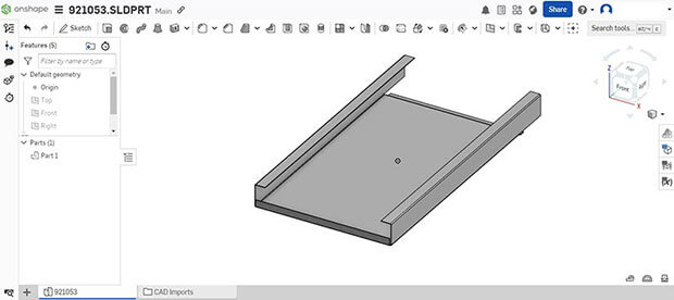 Onshape Web CAD Tool
Utilizing feature-based modeling also aids in maintaining precision, as it creates a history of operations that can be edited, ensuring measurements are consistent and traceable.
CAD also simplifies the calculation of bend allowance, crucial in sheet metal fabrication. It provides flexibility in viewing bending results specific to the data input, with options to create and edit bend tables using its integrated editor
By integrating these sheet metal drafting and modeling techniques into the workflow, fabricators can consistently produce parts that meet high quality standards.
Impact of inaccuracies in fabrication drawing on final product
Inaccuracies in sheet metal drawings have a cascading effect on the entire production process, leading to costly reworks and compromised product quality. Inaccurate drawing details adversely impacts the entire process where even slight deviations result in components that do not fit together properly, causing assembly issues or functional defects.
Burr formation, for instance, occurs when a thin ridge or edge is left on the part after trimming, often due to misalignment or excessive force. Cracks and tears may form at the edges of the part, often due to lack of support during trimming or brittleness of the material.
Distortions are another concern, where the part warps or bends out of its intended shape, often due to uneven or excessive force or rapid release from the die.
Most of these challenges relate to fit and assembly issues, functional defects, aesthetics, tolerance stack-up and durability.
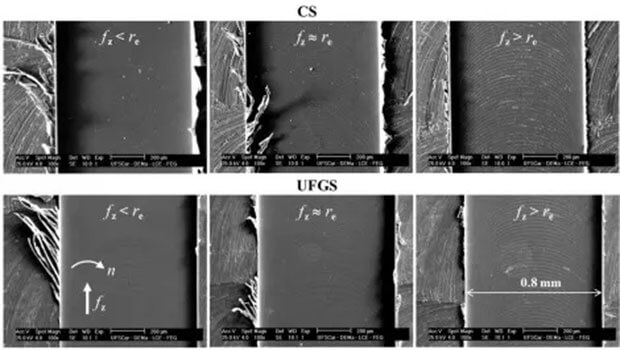 Burr formation due to inaccurate alignment (Source: proleantech.com)
Overcoming these challenges require ensuring the accuracy through rigorous quality control methods and use of advanced CAD/CAM software. You can achieve this by hiring an adept inhouse team or choose an outsourcing partner for sheet metal CAD drafting and modeling.
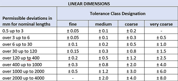
Industry standards for dimensional tolerances (ISO standards)
Dimensional tolerances are critical to ensuring that sheet metal parts fit together correctly and function as intended. They define the permissible limits of variation in a physical dimension which is a very crucial quality metric in sheet metal fabrication drawings.
The International Organization for Standardization (ISO) provides globally recognized standards in sheet metal fabrication through ISO 2768-1:1989. It outlines general tolerances for various aspects of sheet metal parts, including:
-
Linear Dimensions: This category includes tolerances based on the nominal length ranges in millimeters. There are different tolerance classes, namely fine (f), medium (m), coarse (c), and very coarse (v).

-
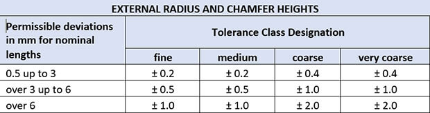
External Radius and Chamfer Heights: Similar to linear dimensions, these also have tolerances based on nominal length ranges and are divided into the same four tolerance classes.

-
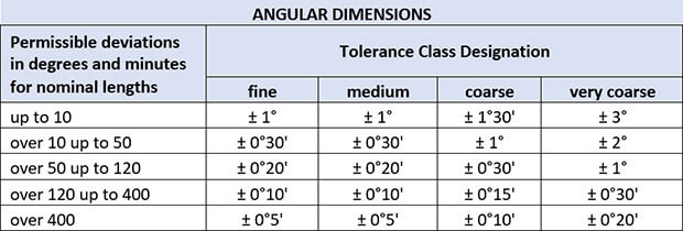
Angular Dimensions: These tolerances are specified for various ranges of nominal lengths in degrees and minutes. The tolerance classes are the same as for linear dimensions and external radius/chamfer heights.

-
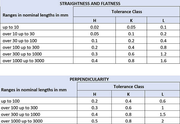
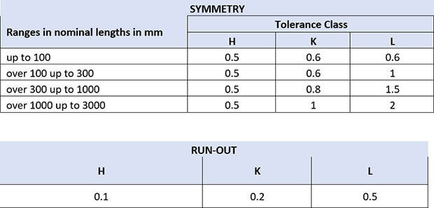
Geometric Tolerance: This includes tolerances for aspects such as straightness, flatness, perpendicularity, symmetry, and runout. These are also classified into three tolerance classes: H, K, and L.


Adherence to these standards ensures parts are produced with acceptable precision, maintaining interchangeability and functionality. Fabricators must implement a robust quality control system in sheet metal fabrication detailing with calibrating measuring tools. Training personnels should interpret and apply these standards accurately throughout the manufacturing workflow.

How AI is impacting design development for sheet metal fabrication
- Optimize CAD design process with AI for metal fabrication
- Accelerate prototyping; ensure quality and compliance with AI
- Reduce scrap and minimize environmental footprint
Quality Metric 2: Measuring Material Specification Accuracy
Material specification accuracy is a critical quality metric in sheet metal fabrication drawings, as it directly impacts the functionality and durability of the final product. Following are the important aspects of this quality metric:
- Material Type and Thickness: Materials have distinct properties that affect both manufacturing and product performance. Material thickness is crucial because it determines strength and flexibility. It’s vital to keep these dimensions within set tolerances to ensure the part works correctly.
- Grain Direction: For parts that need bending or have visual specifications, grain direction affects strength and appearance. It’s important to specify grain direction on the design for parts that require a specific finish, to guarantee the final product meets expectations.
- Finish Details: Finish details, including specific requirements like brand and number for powder coating, are critical for achieving the desired aesthetics and functional characteristics of the part. Specifying the type of finish (matte, textured, smooth, gloss, or semi-gloss) helps the shop to narrow down options and deliver the correct finish.
- Key Specifications and Tolerances: Accurate and detailed documentation of key specifications and tolerances helps in identifying potential manufacturing issues early in the design process, allowing for adjustments that improve the final product’s manufacturability.
- Compliance with Standards: The material should meet industry-specific standards (like ASTM, ISO, etc.) to ensure quality and compatibility with the intended application.
The consistent application of these processes helps to minimize waste, reduce rework, and ensure that each fabricated component meets the precise requirements set forth in the design drawings.
Standardization of material specification (reference to ASTM or ISO)
In sheet metal fabrication, the standardization of material specification ensures consistency, safety, and compliance with industry standards.
Utilizing references such as the American Society for Testing and Materials (ASTM) or the International Organization for Standardization (ISO) provides a common language for defining material properties and grades, which directly impacts key quality metrics. Following are a few important instances:
-
ISO Standards: ISO 2768 is a prevalent standard in sheet metal fabrication, covering tolerance requirements for multiple industries. This standard helps in balancing costs and processing capabilities.
Additionally, ISO 9001 specifies the requirements for a quality management system (QMS), ISO 14001 provides a framework for managing environmental responsibilities, and ISO 3834 covers the quality requirements for fusion welding of metallic materials, including sheet metal fabrication.
-
ASTM International Standards: ASTM develops and publishes standards relevant to sheet metal fabrication. Key ASTM standards include:
- ASTM A36, which covers the chemical and mechanical requirements for carbon steel shapes, plates, and bars used in general structural applications.
- ASTM A1011, specifying the general requirements for hot-rolled, carbon, structural, high-strength low-alloy, and high-strength low-alloy with improved formability steel sheet and strip.
- ASTM A653, covering the general requirements for steel sheet, zinc-coated (galvanized) or zinc-iron alloy-coated (galvannealed) by the hot-dip process.
CAD design engineers or drafters should specify the standards used [ASTM or ISO or any other] in the , alongside other material properties like thickness, coatings, or finishes to minimize variations and non-conformities.
By standardizing specifications, fabricators enhance traceability, promote interoperability among components, and facilitate quality control processes such as First Article Inspection (FAI) and Production Part Approval Process (PPAP).
Software features for accurate material specification in CAD
In sheet metal fabrication CAD software offers advanced features such as automatic gauge adjustment, through which the software can adapt the design to the correct thickness of the metal, preventing costly errors in production.
Material library integration allows designers to select from a pre-populated list of materials, ensuring that the chosen material meets the necessary standards and properties. The use of real-time cost estimation tools within CAD can inform designers about the financial impact of their material choices, promoting cost-effective decisions without compromising quality.
Additionally, tolerance setting features enable the specification of acceptable variations in dimensions, which is critical for components that must fit together precisely. For enhanced clarity and communication, annotation tools can be used to add detailed notes and instructions regarding material specifications directly onto the drawings.
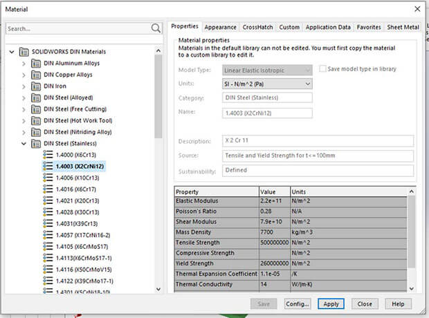 Material specification table in SolidWorks
Essential CAD software for sheet metal fabrication Autodesk Fusion 360 and Solid Edge come equip with features especially for this. Fusion 360 offers 2D and 3D design, precise modeling, bend commands, and integrates CAD and CAM for smooth design to manufacturing workflow. It also has parametric modeling, sheet metal forming simulation, and supports laser cutting and welding.
Solid Edge enhances the efficiency of the product development process. Both the softwares have document and inventory management, cost estimation, and materials management features to boost sheet metal fabrication productivity.
Quality Metric 3: Measuring the accuracy of Surface Finish and Texturing details
The accuracy of surface finish and texturing details in sheet metal design is typically measured and specified during the drawing stage using various parameters and standards. This process is crucial for ensuring the functionality, aesthetics, and durability of the final product.
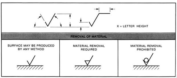
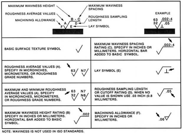
This specification is achieved by symbols and notations that are part of the standardized language used in engineering drawings to communicate the level of finish required on each surface of a part, which directly impacts its functionality and aesthetics.
- Basic Surface Texture Symbol is the fundamental symbol for surface texture, which can be modified with additional marks to convey relevant information.
- Roughness Average Value is often given in microinches or micrometers and indicates the average surface roughness. The roughness grade number can also be used, which corresponds to a specific range of Ra values.
- Maximum Waviness Spacing relates to the spacing between the waviness profile peaks and can be specified in the drawings.
- Roughness Sampling Length or Cutoff specifies the length over which the roughness is evaluated. It can be indicated when it differs from the standard length.
- Lay Symbol indicates the direction of the predominant surface pattern, which can be important for certain applications.
- Machining Allowance specifies additional material left on the surface to be removed during a finishing process.
These notations are vital for the precise communication of how a part should be machined and finished.
Techniques for accurately depicting surface finishes in CAD
A variety of techniques can be employed to ensure that surface finishes are represented with precision. These are essential to communicate the desired finish to fabricators and ensure the final product meets the required specifications.
Here are some of these techniques:
- Texture Representation: CAD software often allows users to apply textures that mimic various surface finishes. This visual cue helps to differentiate between different finishes like matte, gloss, brushed, or mirror finish.
- Layer and Color Coding: Different layers or colors can be used in the CAD drawing to indicate different surface finishes. This coding system is a standard practice in many industries and helps in easy identification.
- Annotations and Notes: Detailed notes and annotations directly on the CAD drawing can specify the type of finish, the process to achieve it, and any relevant standards or specifications.
- Hatching Patterns: Using different hatching patterns can visually represent different surface finishes. This is particularly useful in black and white drawings or in situations where color coding is not feasible.
- Cross-Sectional Views: Including cross-sectional views in the drawing can provide additional detail about the surface finish, especially when the finish affects the dimensions or fit of a part.
- Standards and Symbols: Adhering to industry standards and using universally recognized symbols for surface finishes ensures clarity and consistency.
- Scale and Detailing: It’s important to balance the level of detail with the scale of the drawing. Overly detailed finishes on a small-scale drawing can lead to confusion.
These methods, when combined, enhance the clarity and accuracy of the fabrication drawings, ensuring that quality metrics for surface finishes are met with precision.
Standards for surface finish in sheet metal fabrication (e.g., Ra values)
In technical drawings, surface roughness is often represented by numerical values indicating the characteristics of the roughness profile. The most frequently specified roughness parameters are Ra (average roughness) and Rz (mean roughness depth).
Ra is defined as the average variation of the roughness profile from the mean line, which means the Ra value is typically lower than the actual height of the roughness variations.
For general applications, a surface finish with an Ra value between 32 to 125 microinches is standard, while more demanding applications, such as those requiring reduced friction or high gloss, may necessitate finer finishes with Ra values as low as 4 to 16 microinches.
Fabricators achieve these finishes through a variety of processes, including grinding, sanding, buffing, and polishing. Each technique is chosen based on the material, the desired finish, and cost considerations. The industry adheres to standards such as those outlined by the American Society of Mechanical Engineers (ASME) B46.1 for specifying and measuring surface texture, ensuring consistency and quality across different fabrication projects.
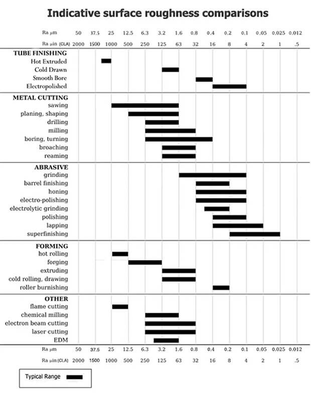
Surface roughness chart for different techniques (Source: wevolver.com)
Achieving the specified surface finish requires adherence to process controls and regular inspection, often utilizing profilometers to measure the Ra values and ensure compliance with the design requirements.
Quality Metric 4: Measuring Tolerance Representation accuracy
Measuring Tolerance Representation Accuracy is critical in sheet metal fabrication drawings, to ensure that fabricated parts meet design specifications and fit together correctly during assembly.
Sheet metal tolerances refer to the maximum permissible deviation range in the dimensions during sheet metal processing. Ensuring that each product stays within this tolerance range is essential for maintaining quality standards.
A practical approach to tolerance specifications involves aligning these specifications with the actual requirements of the sheet metal part. This means avoiding unnecessary precision that does not add value to the function or structure of the product. Proper alignment ensures that the tolerances are not just theoretically accurate but also practically relevant.
Techniques such as Geometric Dimensioning and Tolerancing (GD&T) are employed to clearly communicate the allowable variation in part dimensions.
The workflow often includes a quality check where a sample of parts is measured and recorded. Data from these measurements are then compared against the tolerance requirements detailed in the drawings. If discrepancies are found, adjustments are made to the fabrication process to improve accuracy.
Geometric Dimensioning and Tolerancing (GD&T) in CAD
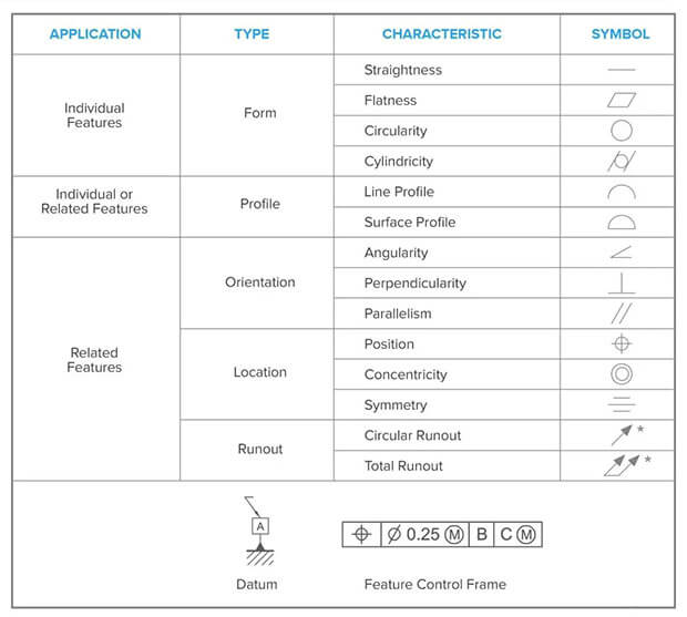
Symbols used in GD&T (Source: formlabs.com)
Geometric Dimensioning and Tolerancing (GD&T) is a crucial tool used in CAD to ensure that sheet metal fabrication drawings meet key quality metrics. GD&T helps in defining the geometry of parts and assemblies, which is essential for maintaining consistency in the following quality metrics:
- Dimensional Accuracy: GD&T provides a comprehensive system for defining dimensions and tolerances, ensuring that every part fits together as intended.
- Form Tolerance: By specifying form constraints, GD&T ensures that the flatness, straightness, roundness, and profile of sheet metal parts are within acceptable limits.
- Orientation Tolerance: GD&T controls the angularity, perpendicularity, and parallelism of features, which is vital for parts that must align correctly with other components.
- Location Tolerance: It defines the exact position of features, which is critical for the functionality of interconnecting parts.
- Repeatability and Interchangeability: GD&T standards allow for parts to be manufactured consistently over time, which is key for replacement and maintenance.
By incorporating GD&T into CAD processes, engineers can communicate complex geometric constraints and ensure that all these quality metrics are adhered to, reducing the likelihood of errors and rework in the fabrication process.
Best practices for indicating tolerances to avoid fabrication errors
In sheet metal fabrication drawings, clearly indicating tolerances is crucial to avoid fabrication errors. Here are 10 best practices:
- Use Standard Tolerance Notations: Adhere to industry standards such as ISO or ANSI for tolerance notations. This ensures that your tolerances are universally understood.
- Specify Tolerances Clearly: Place tolerance notations near the dimensions they apply to. Avoid clustering them in one area of the drawing, which can lead to confusion.
- Consider Material Properties: Different materials have different tolerances due to their properties. For instance, stainless steel might have different tolerance levels compared to aluminum.
- Account for Bending and Folding: Bends in sheet metal can affect dimensions. Specify tolerances for bend angles and locations.
- Highlight Critical Dimensions: Some dimensions are more critical than others in terms of functionality and fit. Make these tolerances more stringent and highlight them on the drawing.
- Use GD&T Where Appropriate: Geometric Dimensioning and Tolerancing (GD&T) can be more effective in conveying complex geometrical tolerances and relationships.
- Include Notes on Fabrication Methods: Different fabrication methods can impact achievable tolerances. Include notes on preferred methods if they affect the final dimensions.
- Review and Update Regularly: As fabrication methods evolve, so should your tolerances. Regular reviews of tolerance practices can help in maintaining accuracy.
- Communicate with Fabricators: Often, fabricators can provide insights into what tolerances are achievable and cost-effective. Engaging them during the design process can prevent errors.
- Use Templates and Checklists: To ensure consistency across all your drawings, use standardized templates and checklists.
Indicating tolerances in sheet metal fabrication drawings revolve around clear communication, understanding the manufacturing process, adhering to international standards, and providing comprehensive details in the drawings. These practices help in avoiding fabrication errors and ensuring that the parts meet the design specifications.
Quality Metric 5: Measuring Welding and Joining Details Accuracy
In sheet metal fabrication, the precision of welding and joining details is important for the integrity and function of the final product. To measure this accuracy, the following factors are considered:
- Weld Type and Size: The drawings should specify the type of weld (e.g., spot, seam, MIG, TIG) and its dimensions accurately. This includes the length, width, and depth of the weld.
- Location and Orientation: The precise location and orientation of the welds on the parts are essential. Misplaced welds can lead to structural weaknesses or assembly issues.
- Surface Preparation: Proper surface preparation for welding, such as cleaning and pre-heating, should be indicated if necessary. This ensures strong and defect-free welds.
- Welding Standards Compliance: Drawings must adhere to relevant welding standards (like AWS or ASME) to ensure consistency and quality.
- Inspection Criteria: Criteria for inspecting welds, such as visual inspection, x-ray, or ultrasonic testing, should be defined to ensure weld integrity.
These details ensure that the fabricated sheet metal components meet the required strength, durability, and precision.
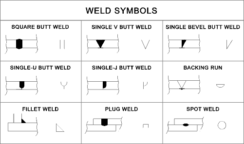
CAD symbols and conventions for welding/joining
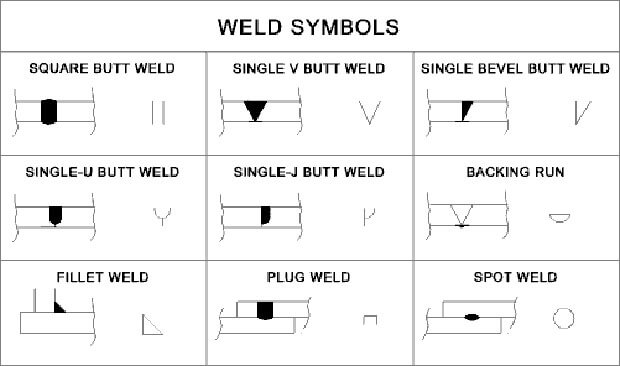
Different weld symbols for sheet metal fabrication (Source: samsfabrications.co.uk)
The clarity and precision of CAD symbols and conventions for welding and joining are crucial in sheet metal fabrication drawings. These symbols, standardized under AWS (American Welding Society) specifications, communicate the type of weld, its size, and length, among other details, without cluttering the drawing.
Effective use of these symbols ensures that:
- Fabricators understand the exact requirements for welding, reducing errors in the assembly process.
- Inspectors can verify compliance with the design specifications during quality checks.
- There is a reduction in manufacturing time due to fewer questions and clarifications needed on the shop floor.
For example, a fillet weld is represented by a triangular symbol, whereas a square butt weld is shown with double straight lines. The leg length or size of the weld is denoted to the left of the weld symbol, while the length and pitch (if required) are indicated to the right.
Proper interpretation of these symbols is critical to the integrity of the final product.
By adhering to these conventions, fabricators can mitigate the risk of structural failures or non-conformities, thereby upholding the integrity of the sheet metal fabrication process.
Impact of these details on fabrication quality and structural integrity
The accurate measurement of the welding and joining details in sheet metal fabrication drawings directly influences the fabrication quality and structural integrity of the final product. Following are the major impacts:
- Precision and Strength: Accurate measurements ensure that welding and joining are executed precisely, which is vital for the strength of the metal structures. Inaccurate measurements can lead to weak joints, which may fail under stress.
- Alignment and Fit: Proper measurement ensure that parts align correctly and fit together as intended. Misalignment due to inaccurate measurements can lead to issues in assembly and functionality.
- Consistency and Reproducibility: Accurate measurements contribute to consistency in production, allowing for the reproduction of parts or structures with the same quality and specifications. This is especially important in large-scale production or in projects requiring uniformity across multiple components.
- Safety and Compliance: In many industries, there are strict regulations regarding the structural integrity of metal fabrications. Accurate welding and joining measurements ensure compliance with these safety standards, reducing the risk of accidents and legal issues.
- Aesthetics and Finish: Accurate measurements also affect the aesthetic quality of the final product. Neatly executed welds and joins, which are a result of precise measurements, enhance the visual appeal of the metal fabrications.
- Cost and Time Efficiency: Accurate measurements can reduce waste and the need for rework, thus saving both time and resources in the fabrication process.
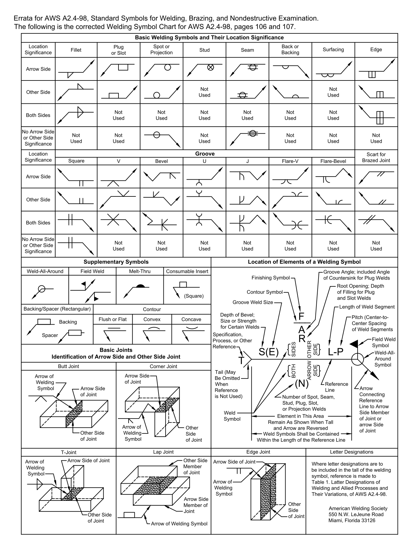
Reference to welding/joining standards (AWS standards)
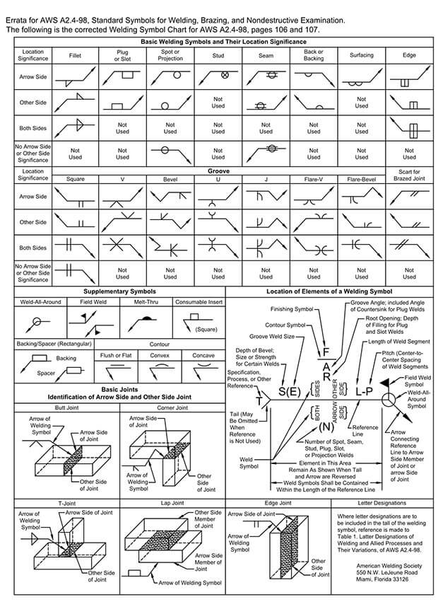
Standard Welding symbol chart as per AWS (Source: blog.draftsperson.net/)
In sheet metal fabrication, specific standards and codes are essential for ensuring quality and consistency in welding and joining processes. The American Welding Society (AWS) plays an important role in setting these standards.
Here are some key points about the AWS standards relevant to sheet metal fabrication:
- AWS A2.4: Standard Symbols for Welding, Brazing, and Nondestructive Examination: This publication provides extensive knowledge on the language of welding symbols, which is crucial for interpreting metal fabrication drawings.
- AWS D9.1/D9.1M:2018 – Sheet Metal Welding Code: This specific code addresses the arc and braze welding requirements for nonstructural sheet metal fabrications. It encompasses commonly welded metals available in sheet form and includes requirements and limitations governing procedure, performance qualification, workmanship, and inspection standards.
- Scope of AWS D9.1:2018: This code applies to sheet metal thicknesses up to and including 0.2391 inches (6.07 mm). It is used for tasks such as attaching accessories and components, joining or attaching members for stiffening, supporting, or reinforcing the sheet metal, and covers both arc welding (the joining of metals by melting and intermixing).
- Extensive Range of AWS Standards: The AWS has developed over 350 standards for various welding practices and procedures. One of the most referenced is the D1.1 Structural Welding Code – Steel. These standards are developed by expert committees and are ANSI-approved, ensuring they meet rigorous quality and safety benchmarks.
These standards and codes are integral to the sheet metal fabrication industry, guiding professionals in maintaining the highest levels of quality, safety, and efficiency in welding and joining processes.
Implementing and Monitoring Quality Metrics
In sheet metal fabrication, it is essential to ensure that drawings meet the industry standards and client specifications. Techniques such as regular audits of the drawings and the fabrication process help in identifying any discrepancies early on.
Utilizing CAD Software allows for precise measurements and tolerances, which can be automatically checked against pre-set standards. Statistical Process Control (SPC) methods enable fabricators to monitor the consistency of the dimensions and geometries throughout the batch production.
Finally, it is crucial to establish a Feedback Loop with the shop floor operators to continuously improve the drawings based on real-world manufacturing challenges. By focusing on these techniques, manufacturers can uphold the highest quality in their sheet metal fabrication drawings.
Role of CAD software in quality control and assurance
CAD software accurately represents sheet metal parts, ensuring dimensions are within tolerances. It manages geometric tolerances effectively by predicting and adjusting for material deformation during fabrication.
CAD precisely defines surface textures and patterns, linking them to machining processes for the desired surface quality. It also optimizes material use by minimizing waste and simulates assembly to identify fit and function issues before production.
This enhances precision and efficiency in quality assurance, resulting in consistent, high-quality sheet metal outputs.
To maintain quality in sheet metal fabrication drawings, implement version control to track changes and keep an audit trail. Use automated error detection to identify inconsistencies. Conduct regular peer reviews for cross-examination of drawings, encouraging collaborative error reduction.
Incorporate customer feedback directly into designs for real-time updates. These techniques should be part of a continuous improvement workflow, following a plan-do-check-act cycle, to constantly enhance quality with each project iteration.
Conclusion
Understanding the importance of quality metrics in sheet metal fabrication drawings is crucial for ensuring the production of high-quality, reliable, and consistent products. The five key metrics—dimensional accuracy, tolerance specifications, material specifications, surface finish, and welding symbols—serve as a comprehensive guide for both designers and manufacturers to assess and maintain the quality of their work.
With a clear understanding and proper implementation of these quality metrics in the sheet metal fabrication from the drawing phase, stakeholders can significantly reduce errors and rework, optimize production time, leading to improved credibility and a better competitive edge in the marketplace.
Reduce errors and enhance efficiency of your sheet metal fabrication project.
Get expert guidance to improve quality and efficiency for a competitive edge.


