
- 2D drafting processes are insufficient for precision and speed needed for modern sheet metal design.
- 3D CAD eliminates interpretation errors, automates flat pattern generation and enables forming process simulation for better manufacturing.
- 3D CAD drawing helps manufacturers reduce material waste, build faster design cycles and collaborate better through parametric modeling and direct CAD-to-CAM processes.
Table of Contents
- Challenges with traditional 2D methods in sheet metal design
- Core advantages of 3D CAD in sheet metal product design
- Using 3D CAD to optimize sheet metal fabrication
- Improved integration and estimation using 3D CAD for sheet metal product design
- The future of 3D CAD modeling in sheet metal
- Conclusion
Design complexity in the sheet metal industry is rising every day with the pressure of customization and other demands including faster production, which is difficult to tackle solely with 2D drafting. This is where sheet metal design services step in, with specialized 3D CAD drafting and designing. The traditional methods may be fine for basic geometries but fall short when it comes to modern complex assemblies, tight tolerances, and rapid prototyping capabilities.
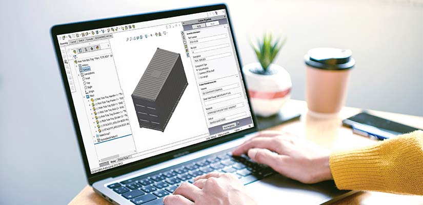
Designers have been adopting 3D CAD drawing for sheet metal product design in recent years because CAD helps to address these operational challenges through advanced modeling capabilities. It lets you visualize, analyze, and optimize designs before physical production begins.
Many 3D CAD drawing services provide end-to-end solutions for manufacturing design and workflow analysis, while some provide specific assignment-based services. Here, we’ll discuss how using CAD software for sheet metal design helps to gain measurable reductions in errors, waste, and time.
Challenges with traditional 2D methods in sheet metal design
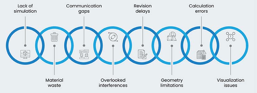
Professionals using 2D drafting methods struggle with the following challenges in modern sheet metal fabrication environments:
- Difficulty in visualizing complex 3D forms and assemblies: Orthographic projections do not show spatial relationships well, leading to misinterpretation of design intent and assembly sequence.
- Error prone in bend allowances and flat patterns: Manual calculations for bend deductions and K-factors introduce variability and inaccuracies, especially for complex shapes with multiple bends.
- Can’t represent intricate geometries and features: 2D can’t convey complex contours, non-linear bends or specialized forming features common in advanced sheet metal drafting.
- Manual revisions and updates for design changes take too long: Changes require redrafting across multiple views, bottlenecking design iteration cycles, and extending project timelines.
- Can’t detect interferences or assembly issues pre-production: 2D cannot show spatial conflicts between parts until physical prototyping or production, resulting in rework.
- Can’t communicate design intent clearly to fabrication teams: Variations in interpretation between designers and manufacturers lead to production errors and quality issues.
- Inefficient material utilization due to manual nesting approximations: Without flat pattern data, material optimization is an estimate, resulting in waste and higher costs.
- No support for simulating forming processes or stress analysis: Traditional methods cannot predict material behavior during forming, limiting design optimization.
Core advantages of 3D CAD in sheet metal product design
Using 3D CAD in sheet metal workflows brings significant benefits to design, manufacturing, and quality assurance through the following main advantages.
Better design visualization and understanding
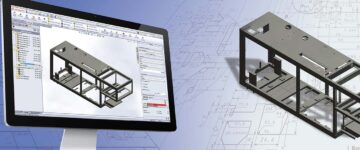
3D CAD drawings provide a holistic, interactive view, eliminating ambiguity in 2D interpretation. For example, SolidWorks’ dynamic cross-sectioning and Inventor’s exploded views make complex assemblies easier to view and understand.
3D visualization allows you to spot design flaws, interferences, and assembly clearances before physical prototyping, reducing costs and development time. Interactive model review using lightweight viewers allows all stakeholders, regardless of CAD skills, to review designs together.
Markup tools, commenting features, and animated views enable clear communication between design teams, manufacturing, and clients, democratizing the review process and ensuring design intent is aligned.
Fewer design and manufacturing errors
3D CAD modeling for sheet metal design eliminates 2D drawing interpretation errors through precise geometric data that can be sent directly to manufacturing equipment. Automated interference checking in tools like CREO detects assembly conflicts.
Manufacturability validation tools check in real time for sheet metal fabrication and flag features too close to bend lines or where there are not enough relief cuts.
Advanced CAD software for sheet metal ensures design intent is translated through integrated data management. The 3D model is the single source of truth and drives CAM programming for laser cutters and press brakes. This helps maintain design intent while eliminating manual dimensioning errors.
Precision in flat pattern generation
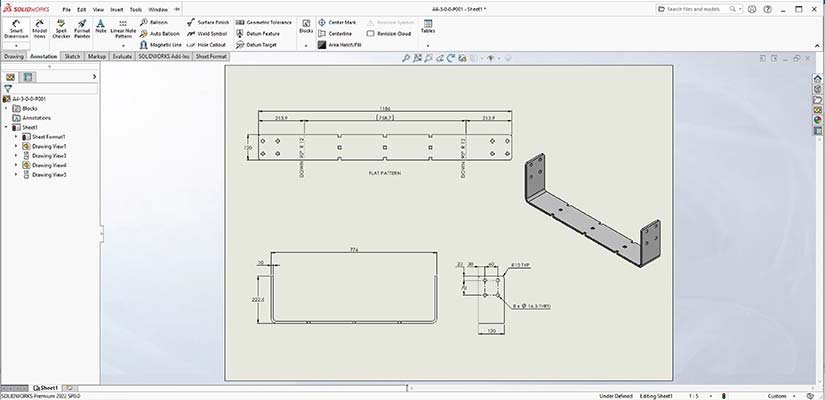
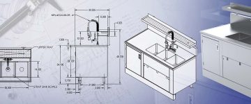
Modern sheet metal CAD drawings are based on algorithms for automated flat pattern generation, taking into account material deformation during bending. Unlike manual approximations, using CAD, such as Inventor’s unfolding tools, gives you dimensionally correct patterns for complex shapes with multiple bends and varying angles.
Bend allowance, deduction and K-factor calculations use material databases and customizable bend tables of CAD tools like SolidWorks. Advanced systems adjust K-factors based on real-world data to minimize material waste.
This extends to non-linear bends, lofted shapes and material specific behaviors like springback, for precision levels not achievable through traditional methods for tight tolerance requirements.
Speed up production with accurate 3D metal designs.
Our models mean better fit, fewer revisions, faster delivery.
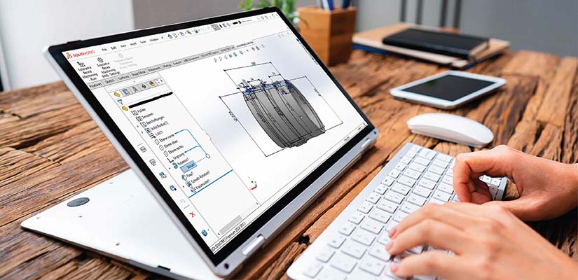
Simulating sheet metal forming processes
Using 3D CAD drawing for sheet metal lets you use advanced simulation modules that predict critical material behavior: springback, elastic recovery, material thinning and wrinkling.
Simulation with CAD tools like CREO will show you problem areas and allow you to optimize your design for better formability. Virtual testing will validate your tooling and forming sequence without expensive physical prototypes, check for collisions, and optimize multi-stage processes.
You can leverage tools like SolidWorks to determine the optimal operation sequence, punch strokes and clamping forces. These insights help you to optimize your design, adjust bend radii, modify relief cuts and explore material specifications in a virtual environment, so your design is functionally sound and economically viable with reduced scrap rates.
Designing complex geometries and features
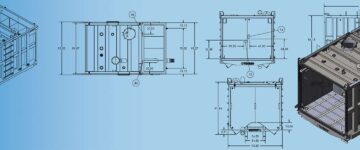
3D sheet metal drafting tools allow for the creation of complex contours, organic shapes and forming features that cannot be defined in 2D.
CAD tools like Inventor help create highly curved edges and specialized elements like louvers and dimples with accurate 3D definition for formability. SolidWorks has advanced tools for robust hems, seams, tabs and joining details with geometric control, automate various hem types, and interlocking features with clearances.
3D CAD helps generate precise weld preparations, including chamfers and bevels. Additional joining details, such as rivet locations and bolt patterns, are also represented with high precision, improving manufacturing accuracy.
Using 3D CAD to optimize sheet metal fabrication
Using 3D CAD goes beyond design creation to manufacturing optimization, customization and production system integration.
Integrating Design for Manufacturing (DFM) and assembly principles
3D CAD modeling has DFM validation tools built in that check designs against manufacturing capabilities and constraints in real time. These tools check material efficiency, assembly sequences, and tooling requirements during design time so that you can optimize production parameters early.
For example, designing an electronic enclosure with multiple bends requires validation against available press brake tooling and a minimum bend radius to avoid custom tooling requirements.
Integrating manufacturing rules and constraints directly into the design environment prevents non-manufacturable features. Designers get instant feedback on standard tooling availability, minimum bend radii, and material-specific limitations, so designs stay within production capabilities.
Advanced DFM tools in 3D CAD also offer part consolidation opportunities, where multiple components can be combined into one sheet metal part, reducing assembly time and improving product reliability.
Leveraging parametric design for customization
Parametric modeling in CAD for sheet metal allows the creation of intelligent part families and configurable product templates. These systems keep design relationships and constraints while allowing a rapid change of dimensional parameters, facilitating mass customization without extensive redesign.
For example, a parametric model of an industrial conveyor cover system can automatically generate different lengths and widths while keeping bend radii, reinforcement ribs, and access panel configurations across all variants.
Sheet metal product design benefits from the parametric approach in the following ways:
- Automated generation of multiple size variants while keeping manufacturing constraints
- Rapid response to customer requirements through configurable templates
- Design consistency across product families with automatic propagation of changes
Parametric approach ensures design integrity through modification cycles, allowing businesses requiring multiple configuration options to design efficiently.
Streamlining CNC programming and tooling
Direct data transfer from 3D CAD drawings to CAM systems eliminates programming errors and reduces setup time for laser cutters, punches and press brakes. The integrated workflow keeps geometry accurate while generating optimized toolpaths based on material and machine capabilities.
For example, a complex bracket design with cutouts and multiple bends can be programmed automatically, generating nesting and bend sequences that minimize material waste and production time. This digital workflow eliminates manual data entry and transcription errors and provides real-time feedback on manufacturability.
Advanced CAD/CAM integration means faster and more accurate design of jigs, fixtures and forming tools. 3D design data provides precise geometric references for tooling development, reduces design time, improves tool accuracy and ensures part quality.
Top-down parametric modeling for sheet metal assemblies
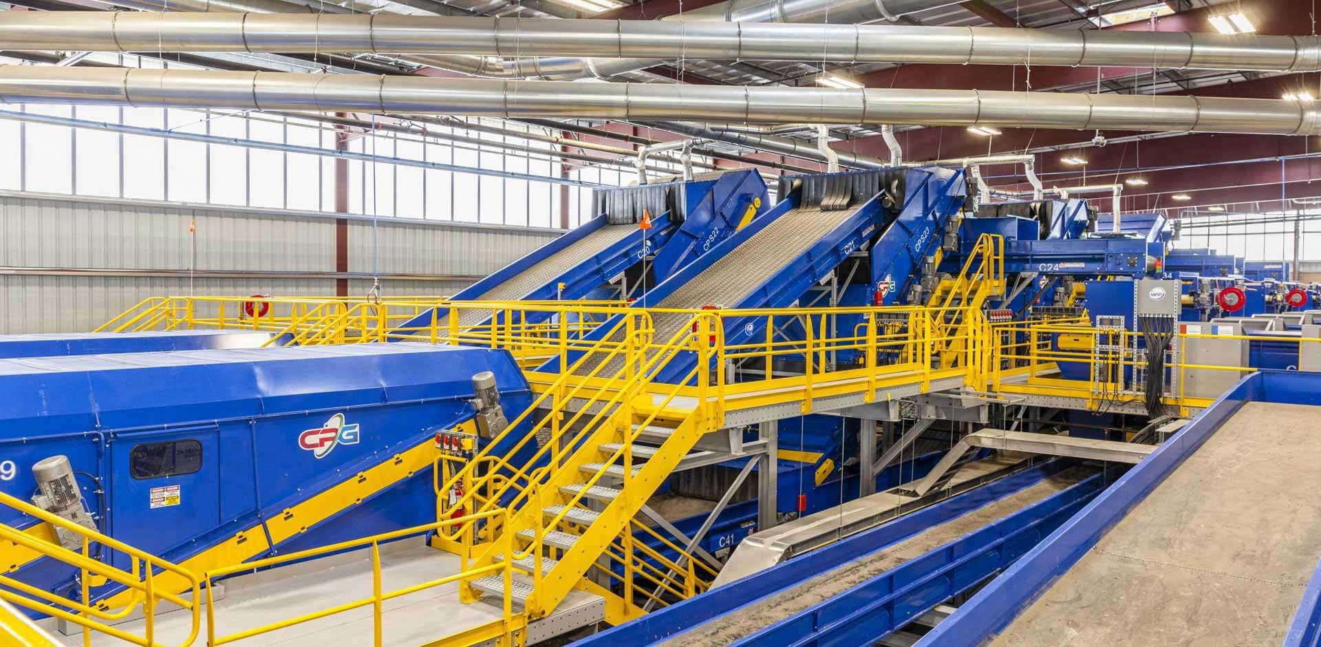
An Irish recycling and material handling equipment manufacturer was struggling to design complex sheet metal assemblies like hoppers and support structures. Minor changes to conveyor layouts would require a lot of rework, resulting in delays and errors.
HitechDigital used top-down parametric modeling in Creo to create master skeleton models to drive design intent across all components. This allowed for synchronized updates, reduced manual intervention and ensured consistency across the assembly.
The final deliverables led to:
- 50% fewer design iterations
- Faster design-to-manufacture cycle
- More flexibility in layout changes
Design smarter parts with DFM-compliant 3D sheet metal designs.
Save time and costs with parametric modeling in SolidWorks.
Improved integration and estimation using 3D CAD for sheet metal product design
Implementing 3D CAD technology facilitates better data integration, accurate costing and measurable ROI.
Integrating legacy 2D data and imported geometry
Modern sheet metal CAD drawings systems have tools to import and rebuild design intent from 2D drawings and non-native 3D geometry. This allows you to leverage your existing design investment while moving to 3D.
For example, the DXF/DWG Import Wizard allows you to import 2D CAD files (e.g.,dwg or .dxf) directly into SolidWorks. You can select specific views (e.g., front, top, side) and convert them into sketches for 3D modeling.
Geometry repair and preparation tools automatically identify and fix common issues in imported models, so they are ready for sheet metal drafting. The software can rebuild parametric relationships and design intent from imported geometry, so you can use all the advanced modeling capabilities.
Migration tools allow you to convert 2D drawing libraries into 3D models while maintaining design history and revision control. This allows you to modernize your design process without losing valuable historical design data.
Achieving accurate cost estimation and quoting
3D CAD modeling gives you detailed geometric and material data to obtain accurate cost estimation for sheet metal fabrication projects. The software calculates material requirements, machine time estimates, and tooling costs based on actual 3D geometry rather than on 2D drawings.
Integration with ERP and quoting systems makes the estimation process smoother and more accurate. Real-time access to current material costs, labor rates and machine capabilities means quotes reflect actual production costs and market conditions.
Advanced costing modules take into account secondary operations, finishing requirements and assembly time in their calculations. This comprehensive approach to cost estimation gives more accurate quotes and higher profitability, and reduces proposal development time.
Return on Investment (ROI) of 3D CAD
Companies using 3D CAD drawing for sheet metal report measurable improvements in productivity and cost savings. The benefits include a reduction in material waste through optimized nesting and accurate flat pattern development. Faster design cycles mean faster time-to-market for new products and increased design capacity.
The benefits of 3D CAD span multiple operational areas, as shown in the following table:
| Performance area | Key improvements | Operational benefits |
|---|---|---|
| Material utilization | Optimized nesting patterns | Less waste and inventory costs |
| Design efficiency | Automated feature creation | Shorter development cycles |
| Manufacturing quality | Improved design validation | Fewer production errors |
| Collaboration | Centralized data management | Better team coordination |
| Process automation | Direct CAD-to-CAM transfer | Less manual programming |
The reduction in rework and scrap rates directly impacts profitability through better first-pass quality. Better sheet metal drafting accuracy means fewer production errors and higher customer satisfaction.
The future of 3D CAD modeling in sheet metal
CAD software for sheet metal is evolving quickly with the integration of artificial intelligence and machine learning. AI-powered design validation tools automatically identify manufacturing issues and suggest optimizations, simplifying sheet metal product design.
Generative design algorithms create lightweight, material-efficient structures that would be impossible to design traditionally. These algorithms optimize for specific performance criteria while maintaining manufacturability constraints, balancing function, and production efficiency.
Cloud-based CAD enables distributed design teams to work on complex projects simultaneously. Real-time collaboration tools allow for immediate design review and approval while maintaining version control and design integrity across global workspaces.
Data analytics and smart manufacturing principles transform sheet metal fabrication through predictive maintenance, quality monitoring, and process optimization. These technologies use design data and production feedback to continuously improve processes and product quality.
Conclusion
3D CAD drawing services for sheet metal design deliver measurable improvements in precision, efficiency and innovation. Companies using 3D workflows see reductions in errors, material waste and production time and can design more complex products.
The combination of advanced modeling, simulation and manufacturing within modern CAD software for sheet metal gives you more than just the immediate operational benefits. As the industry goes digital, 3D CAD drawing for sheet metal will continue to be essential for companies to stay ahead in the advanced manufacturing markets.
Get fabrication-ready shop drawings aligned to standards.
Detailed views, part numbers, BOMs, and instructions in one set.