
- Detailed millwork drawings reduce errors in design interpretations by accurately communicating design intent across stakeholders, from architect to fabricator and manufacturer.
- A detailing overload in millwork drawings however creates information clutter and difficulty for the shop floor to zone in on relevant information.
- It is important to understand the optimal level of detailing needed in your millwork shop drawings which includes shop floor operational information, material quantity, bought-out parts, Bill of Materials etc.
Table of Contents
Millwork drawings are by far the most effective medium to convert conceptual millwork and joinery design ideas into a physical product. These concept ideas need approvals from architects, designers, and manufacturers before being released for the shop floor.
Thus, any millwork shop drawing would entail tons of information for every stakeholder to understand and interpret design intent and/or raise their concerns. But the process of making detail-rich millwork shop drawings often results in information clutter. One way to avoid information chaos is sharing data that is just sufficient to make informed decisions for every stakeholder.
Understanding Millwork Drawings
Millwork shop drawings are detailed technical drawings that provide specific instructions on how to fabricate and install custom millwork components like cabinetry, doors, and trim. These are your primary communication tool in conveying essential millwork details that provide accurate dimensions, material specifications, and assembly instructions, leaving no room for misinterpretation.
These blueprints are roadmaps for successful fabrication and installation. Precise measurements ensure your millwork integrates flawlessly into its designated space. The material specifications—wood species, finishes and hardware—are your guide for achieving the desired aesthetics and functionality. Detailed millwork plans also define joinery techniques and installation procedures, ensuring a smooth execution from start to finish.
Elevations, sections and detailed perspectives offer a 360-degree view of the design. This multi-dimensional understanding facilitates effective collaboration among architects, designers and craftspeople who bring the vision to life. By providing this holistic representation, millwork drawings guarantee that the final products meet both aesthetic and functional requirements, ultimately creating spaces that are both beautiful and purposeful.
What are the common challenges for achieving optimal millwork detailing?
Millwork drafters often face a variety of challenges when trying to achieve detailed millwork drawings. These include:
- Achieving precision and accuracy: Millwork requires the highest levels of precision and accuracy. Even minor errors in measurements or specifications can cascade into costly reworks and delays in production and installation. Drafters must ensure their drawings are error-free and adhere to industry standards.
- Harmonizing coordination with multiple stakeholders: Millwork projects typically involve collaboration between architects, designers, contractors and fabricators. Drafters must effectively communicate and coordinate with all stakeholders to ensure that the design intent is accurately captured and that all project requirements are met.
- Customization and design variations: Millwork projects involve customized elements and design variations. Drafters must be able to adapt to these unique requirements and accurately document them in their drawings.
- Communication with clarity: Millwork drawings must be clear, concise and easily understood by all stakeholders. Drafters must use appropriate symbols, annotations, and labeling to ensure that their drawings are unambiguous and effectively communicate the design intent.
These factors directly influence both timely deliveries and efficient raw material utilization throughout the project. Inaccurate communication can even lead to defective manufacturing and unsafe installations.
The solution to preventing these issues is ensuring that the right people have access to the necessary information at the right time. Following standard millwork shop drawings best practices helps achieve this.
However, while catering to every stakeholder, these drawings often become overloaded with details. The key is to include only the most essential information in the drawings. So, what exactly constitutes “essential details” in millwork shop drawings?
The answer lies in meeting the needs of reviewers and stakeholders by consolidating all relevant information into a single, comprehensive file.

The Future of Millwork Shop Drawings: Trends and Innovations to Watch
- 3D visualization in CAD enhances conflict detection.
- Macros enable drawing task automation.
- API integration streamlines workflow.
- AR facilitates better visualization and collaboration.
What drawings are typically included in standard millwork submittal?
A standard millwork submittal package typically includes a comprehensive set of drawings that serve as a blueprint for the design, dimensions, materials and fabrication of the millwork components.
These drawings are crucial among the designer, architect, contractor and millworker for clear communication in understanding millwork shop drawing specifications. This ensures that everyone is on the same page.
Key drawings included in millwork submittals include:
-
Shop Drawings:
These are the most important drawings in the submittal package, providing detailed instructions to the fabricator on how to construct and assemble the millwork. These include dimensions, material specifications, joinery details, hardware placement, and any other relevant information.
-
Elevations:
Elevations show the vertical views of the millwork, illustrating the overall design, heights and proportions of each component.
-
Plans:
Floor plans indicating the layout and location of millwork elements. Reflected ceiling plans that show the relationship between millwork and ceiling elements like soffits, coves, or bulkheads.
-
Sections:
Sections provide detailed cross-sectional views of the millwork, revealing the internal construction, joinery details and material thicknesses.
-
Details:
Detailed drawings zoom in on specific areas of the millwork to provide greater clarity on complex connections, profiles or decorative elements.
-
Schedules:
Schedules organize and list specific information about the millwork components, such as materials, finishes, hardware and quantities.
-
Installation Plans:
These plans show how the millwork will be installed on site, including locations, clearances and any necessary coordination with other trades.
-
3D Renderings:
3D renderings or models can be included to provide a more realistic visualization of the final product and assist in design approvals.
The specific drawings included in a millwork submittal vary based on project requirements, complexity and industry standards. Hence, it’s essential to collaborate with the project team to define the necessary documentation for successful millwork fabrication and installation.
Detailing millwork shop drawings for every stakeholder
Since the project architects, designers, and manufacturer or contractor refer to the same files for information exchange, they need purposeful detailing while avoiding information overload.
Let’s quickly delve into the nuances of millwork detailing to efficiently execute any millwork assignment.
Detailing from a designer’s or an architect’s perspective
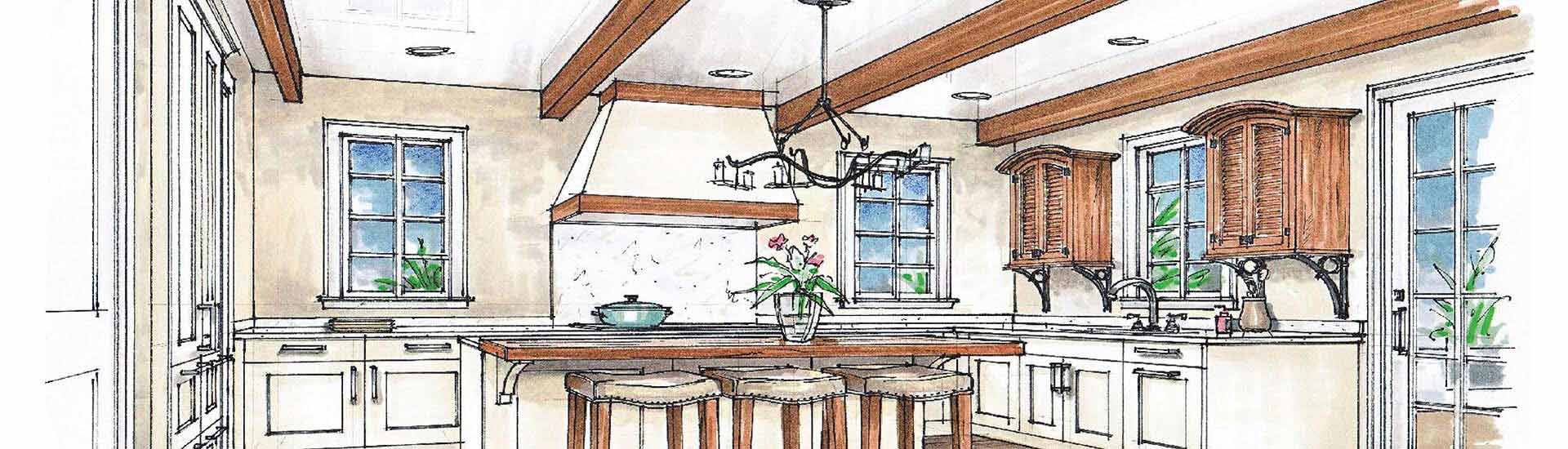
An architect is more concerned about the layout and arrangement of joinery as far as interiors are concerned. Thus their primary focus is on the design intent and orientation of every element.
Joinery drawings are prepared for approvals first by the chief architect to give a go ahead for shop manufacturing. CAD engineers and drafters prepare these drawings by studying the architectural floor plans and conceptual sketches of joinery.
For a joinery designer and manufacturer in the UK, the HitechDigital engineering team developed approval drawings from detailed 3D architectural drawings.
Here are some of the optimal details that the approval drawings warehoused:
- Effective communication about positioning of furniture and decoration
- Drafting details from raised floor plans
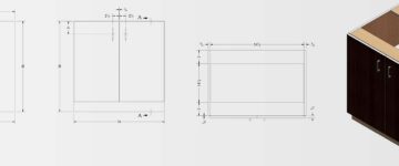
- Outer dimensions and space representation with details like material thickness, laminates etc.
- Elevations for aesthetics, blend with interior designs, architectural theme etc.
- Changes to accommodate the revised dimensions after variations during civil constructions
- Markup changes in drawings suggested by end clients as per their preferences
Once prepared, the detailed CAD submittals and IFC drawings were sent to architect for approvals. Once the architect approved it, shop drawings were developed. This sort of millwork detailing approach eased the drafting work and reduced the time spent.
Get the optimal detailing density in your millwork drawings
Transform design intent into precision-rich production drawings
Detailing from a manufacturer’s perspective
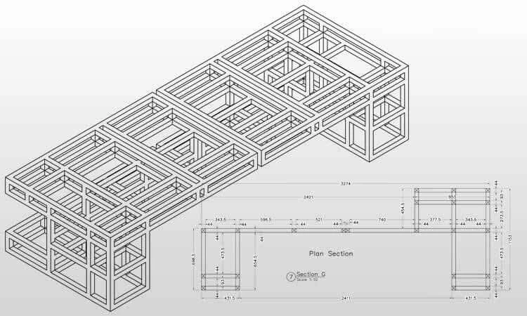
Joinery production, fabrication of sheet metal, and woodworking for any joinery or millwork require a lot of precision. The manufacturer needs sectional views of products on shop floor to get information on preferred machine cuts, edge banding etc.
This ensures a sound understanding of the product’s appearance and the relationship between different levels of parts in an item. Usually, shop floor manufacturers outsource architectural millwork shop drawings to engineering companies with proficiency and experience in executing such projects.
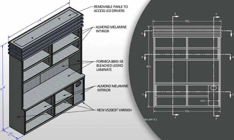
For the same joinery manufacturer referenced earlier, once the approval drawings were approved, our CAD drafting teams developed detailed shop drawings. Alongside, detailed millwork drawings, we also delivered BoMs and laminate schedules for the shop floor engineers that had information regarding:
- Tooling configuration for particular shapes and curves.
- Sheet metal nesting and patterns with cuts, etc.
- Individual part drawings with exploded isometric views.
- Stone drawings as well as DXF files for manufacturing.
- Tooling profile for woodworking, sawing, edge banding.
- Precise manufacturing/machine tolerances and dimensioning for zero errors.
- Markups in detailed shop drawings corresponding to changes in approval drawings.
The standard design dimensions such as screw type, length, and size can be omitted as they may overlap with curtail manufacturing detailing. Also detailing of standard elements must be avoided for clear clutter-free design communication.
These millwork shop drawings use standard nomenclature, abbreviations, and symbolic annotations in detailing to ensure no discrepancies in design communication and strict quality control is achieved.
No resource found with the provided tag.
Detailing from a contractor’s perspective
A contractor defines the scope of work and presides over the project right from inception to the project execution stage.
A contractor ensures that the customer ultimately gets what he is paying for – well within the timelines. He plays an important role in validating the conceptual sketches, submittal drawings, Verified-In-Field (VIF) dimensions, and creation of as-built shop drawings for site installation needs.
Details that an onsite contractor needs in millwork drawings:
- Assembly and installation guides for onsite assistance.
- Detailed views with exploded isometric drawings to ensure every part aligns.
- Assembly parts, trims, fixtures and other fit-out details.
- Tolerances, clearance, quantities, etc. in BoMs.
- Revisions in drawings based on onsite surveys conducted by contractors to update overall dimensions.
Final thoughts
For quality millwork manufacturing, design communication between designers and manufacturers matters which mainly happens through millwork drawings. It can be accurate only when both stakeholders work in close coordination with action-oriented detailing. Further, millwork drawings if done right can help you save up to 30% design cost and accelerate design cycles by up to 70%. HitechDigital’s CAD engineers help you not only avoid clutter but also provide you with the exact amount of detailing at every stage of the project.