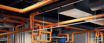

- Accurate and information-rich HVAC ductwork shop drawings are essential for precise system installation, minimizing clashes with building components, and optimizing airflow efficiency.
- Detailed HVAC coordination drawings help reduce errors and ensure compliance with industry standards.
- These drawings facilitate seamless coordination between trades, improving overall project efficiency.
Table of Contents
- Challenges and solutions in shop drawings for HVAC systems
- Understanding the basics of HVAC ductwork shop drawings
- Components of HVAC ductwork shop drawings
- Types of ducts and systems in HVAC shop drawings
- HVAC ductwork sizing and layout considerations
- Software and calculations used for accurate sizing
- Key software features for HVAC ductwork design
- Industry standards in HVAC ductwork design
- Creating accurate HVAC ductwork shop drawings
- Coordination with other trades and systems
- Quality control and common errors in HVAC ductwork drawings
- Emerging trends in HVAC ductwork fabrication drawings
- Conclusion
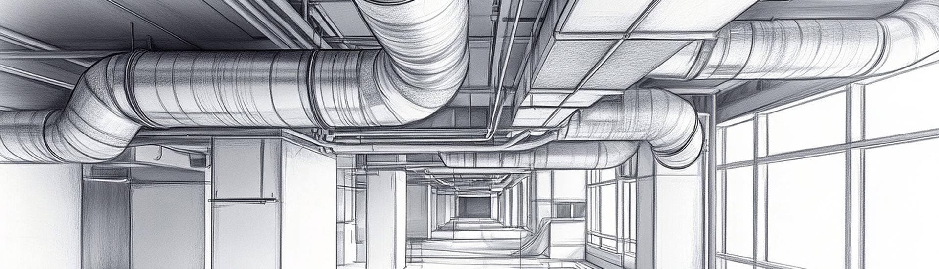
Introduction to HVAC ductwork shop drawings
HVAC ductwork shop drawings are used in construction and installation to provide accurate details for duct sizing, layout, and material needs. They ensure streamlined coordination between disciplines, reduce installation errors, improve HVAC ductwork efficiency, and adhere to regulatory requirements, leading to less rework.
This HVAC coordination drawings guide provides architects, contractors, and engineers with in-depth insights into duct layout, coordination practices, and design standards. These will help improve accuracy, efficiency, and compliance in HVAC ductwork system integration and installation.
Challenges and solutions in shop drawings for HVAC ductwork systems
Creating accurate shop drawings for HVAC ductwork systems can be a complex process, requiring precision and a deep understanding of HVAC ductwork design. Some common challenges faced include:
- Space constraints: Limited space within buildings can complicate duct routing, requiring solutions like reductions in duct size and optimal use of vertical spaces.
- Time pressure: Condensed project schedules require an effective and efficient drafting and approval workflow that expedites revisions and coordination.
- Coordination with other disciplines: Conflicts with trades like electrical, plumbing, fire protection, and structural elements require careful integration and ongoing collaboration.
- Adherence to standards: Constant changes within building codes and industry standards pose challenges to staying compliant and necessitates regular design updates.
- Manage complex layouts: Complex systems with intricate duct design require precision and advanced drafting tools to ensure precision and error avoidance.
Clash-free MEPF models and shop drawings for a multi-storey hospital project save time and cost for engineering contracting company in Ireland

An engineering contracting company from Ireland contacted the team at HitechDigital for MEP modeling regarding a hospital project. Providing mark-up and 2D basic drawings as input, the team utilized BIM tools like Revit and Navisworks along with collaboration tools like BIM360 and drafting platforms like AutoCAD to create coordinated and clash-free HVAC, plumbing and fire protection models with accurate MEP shop drawings. Handing over the deliverables to the client helped-
- Achieve cost savings
- Error-free installation of MEP components
- 98% FTR deliverables.
Understanding the basics of HVAC ductwork shop drawings
Just as construction drawings serve as blueprints for an architectural project, HVAC shop drawings provide detailed specifications for the elements required during installation and fabrication. HVAC ductwork shop drawings play a crucial role as a bridge between design and installation, ensuring the seamless execution of heating, ventilation, and air conditioning systems.
Key differences between construction drawings and shop drawings
| Aspect | Construction Drawings | Shop Drawings |
|---|---|---|
| Purpose | Provide a blueprint of the project. | Details specific elements for fabrication and installation. |
| Level of Detail | Shows a broad project layout. | Focused on the specifics of individual parts or systems. |
| Scope | Covers aspects like architecture, structure, etc. | Illustrates systems like HVAC, electrical, and plumbing. |
| Responsibility | Built by architects and engineers. | Created by contractors and subcontractors for fabrication. |
| Approval Process | Approved by architects, engineers, and building officials. | Reviewed and approved by contractors and engineers. |
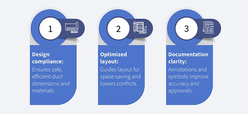
Importance of accuracy in HVAC ductwork shop drawings
Accuracy in HVAC ductwork shop drawings is key for precise duct sizing, improved airflow, and system performance. Inaccurate measurements or misaligned components result in inaccurate installation, airflow issues, system inefficiencies, and expensive corrections that lead to compromised comfort and energy efficiency.
Components of HVAC ductwork shop drawings
Ductwork layout
The ductwork layout in HVAC ductwork shop drawings shows the precise routing and arrangement of ducts within a building. It includes the placement of supply and return air ducts, airflow direction, fittings, junctions, and clearances that ensure effective air distribution. These layouts often align with HVAC ductwork design principles to optimize air distribution and efficiency.
Airflow direction indicators
Airflow direction indicators in HVAC ductwork shop drawings illustrate the path of air through the system, ensuring system efficiency and accurate ventilation. These indicators support duct alignment, prevent airflow problems, and ensure compliance with performance standards and design specifications.
Connections and fittings
Connections and fittings in HVAC ductwork shop drawings are vital to ensure improved airflow and system integrity. These elements include tees, elbows, transitions, offsets, reducers and transitions, which are built to connect ducts that lower pressure loss and manage system performance.
Equipment locations (air handlers, diffusers, etc.)
In HVAC ductwork shop drawings, equipment locations for air handlers, diffusers, and vents are annotated to ensure optimal system functionality. Precise placement is vital for optimal airflow, ease of maintenance, and efficiency, while preventing clashes with various building systems.
Duct sizes, shapes, and materials
These shop drawings detail duct shapes, sizes and materials to ensure efficient compatibility and airflow with building structures. Duct sizes are calculated for air distribution, shapes are selected for an accurate spatial fit, and materials are selected for durability, insulation and regulatory standards.
Understanding symbols, legends, and annotation standards
Understanding legends, symbols and annotation standards is essential for accuracy and clarity. Symbols include airflow direction, equipment and duct types, while legends explain these symbols. Annotation standards ensure uniformity and reduce misinterpretations during installation and maintenance.
Types of ducts and systems in HVAC shop drawings
Understanding the various types of ducts and systems is essential for creating accurate and effective HVAC shop drawings and ensuring optimal performance and compliance with design specifications.
| Duct Type | Description |
|---|---|
| Round Ducts | Effective for airflow and used in open ceilings and large areas. |
| Rectangular Ducts | Used in commercial buildings to maximize space utilization in limited areas. |
| Oval Ducts | Combine round efficiency with a space-saving rectangular shape. |
| Single-Duct Systems | Simplified design to supply air through a single duct network. |
| VAV Systems | Adjust airflow volume to improve energy efficiency in HVAC systems. |
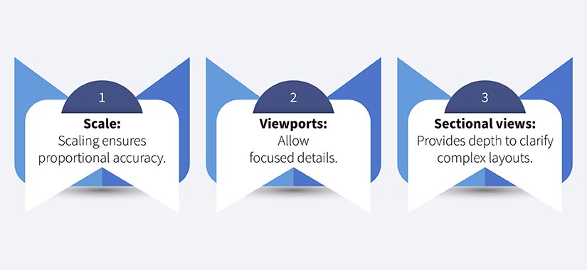
HVAC ductwork sizing and layout considerations
Proper duct sizing and layout ensure the efficiency and performance of HVAC systems. It is important to examine key considerations in duct design, focusing on airflow optimization, energy efficiency, and compliance with industry standards.
Static pressure: Refers to resistance within the duct system that impacts airflow efficiency and fan performance. Accurate sizing lowers pressure loss.
Airflow rates: Indicates air volume through ducts, measured in CFM (Cubic Feet per Minute). Precise rates ensure optimal comfort and ventilation.
Software and calculations used for accurate sizing
Accurate HVAC ductwork sizing relies on software tools like AutoCAD MEP and Revit, which provide precise airflow and static pressure calculations. These platforms optimize layout, improve efficiency, reduce energy loss, and balance air distribution.
Key Software Features for HVAC Ductwork Design
Selecting the right software plays a crucial role in achieving optimal HVAC layouts, as advanced tools provide precise simulations and analysis capabilities. These features aid in optimizing duct layouts by minimizing pressure drops and reducing noise, ultimately enhancing the overall efficiency of the system. Leveraging the right applications ensures seamless integration of design accuracy with practical performance improvements.
| Optimization | Description |
|---|---|
| Reduction in pressure drop | Minimize bends, sharp turns, and duct length to reduce resistance and energy consumption. |
| Lowering noise | Proper placement and insulation of ducts reduce noise and vibrations from the airflow. |
| Enhancing efficiency | Optimized duct sizing and routing improves airflow distribution to ensure efficient heating and cooling. |
Industry standards in HVAC ductwork design
Relevant HVAC standards such as SMACNA, ASHRAE and NFPA deliver guidelines for system design, duct manufacturing, and fire safety. Adhering to these standards leads to greater performance, regulatory compliance and safety in HVAC installations.
Creating accurate HVAC ductwork shop drawings
Accurate HVAC ductwork shop drawings are crucial for successful system installation, as they bridge the gap between design intent and on-site execution. Incorporating best practices during the creation and review process ensures that drawings are precise, compliant with industry standards, and tailored to project requirements. This approach minimizes errors, streamlines fabrication, and enhances collaboration among stakeholders.
Best practices for creating and reviewing HVAC shop drawings
- Follow standards: Adhere to HVAC ductwork design standards for annotations, symbols and duct sizing.
- Coordinate early: Collaborate with other trades to prevent layout issues.
- Utilize BIM tools: Use BIM for accurate layouts and clash detection.
- Detailed layering: Organize layers for equipment, system views, and clear duct.
- Thorough reviews: Double-check airflow, dimensions and alignment before submission.
Layering and color coding for clarity
Layering and coloring in HVAC ductwork shop drawings enhances clarity by organizing elements into unique categories like returns, supply, and exhaust ducts. Each layer or color represents a specific component that aids visual distinction, error reduction, and the simplification of multi-discipline coordination.
Coordination with other trades and systems
Integrating HVAC ductwork drawings with architectural, electrical, and plumbing layouts is vital to prevent clashes and to optimize space. This coordination aligns duct routes with structural elements, plumbing lines and electrical conduits to ensure effective spatial use and lower rework during installation.
Common conflicts in multi-trade coordination and how to resolve them
- Space overlap: HVAC ducts often face interference with plumbing or electrical routes
- Solution: Utilize BIM for quick clash detection early in planning.
- Height constraints: Limited ceiling space causes interferences between various systems.
- Solution: Coordinate with all disciplines to prioritize vertical space allocation.
- Access points: Maintenance area overlaps that block access.
Use of clash detection software for efficient coordination
Clash detection software flags conflicts between HVAC ducts and other building systems like plumbing or electrical. This preconstruction analysis reduces errors, prevents rework, and enhances installation efficiency by ensuring seamless multi-discipline coordination.
Quality control and common errors in HVAC ductwork drawings
Maintaining quality control in HVAC ductwork shop drawings is essential to prevent costly errors and ensure efficient system performance. By identifying and addressing common mistakes, such as misaligned components or inaccurate dimensions, quality control processes safeguard the integrity of the design. This proactive approach enhances reliability, reduces rework, and supports seamless project execution.
Importance of quality control in HVAC ductwork shop drawings
| Aspect | Importance of Quality Control |
|---|---|
| Accuracy | Ensures dimensions, precision, materials, etc. during installation. |
| Compliance | Verifies adherence to HVAC design standards, codes, and specifications to avoid revisions. |
| Efficiency | Improves overall project efficiency by minimizing rework and conflicts during construction. |
Common errors to avoid
Misaligned fittings in HVAC ductwork drawings disrupt airflow, create greater noise, and can cause leaks, which compromises system efficiency and indoor air quality. Accurate alignment leads to a seamless fit, which reduces unnecessary pressure losses and maintenance requirements.
Inaccurate dimensions, another common problem, leads to ducts that do not fit within designated spaces that cause potential clashes with other systems and installation delays. Accurate dimensions prevent conflicts, ensure required airflow, and facilitate expedited installation. Both of these issues highlight the need for stringent measurements, adherence and verification of HVAC design standards within duct shop drawings.
Review and approval process for HVAC ductwork shop drawings
The review and approval process for HVAC ductwork shop drawings ensures that all designs meet the required specifications, codes, and project standards. It is crucial to evaluate the accuracy of dimensions, layout, and system integration, identifying any potential issues before fabrication begins. A thorough review process helps prevent costly mistakes and delays, ensuring that the final drawings are ready for seamless installation.
Some of the steps include:
- Initial draft: Ensure the drawings meet basic project specifications and design needs.
- Multi-discipline coordination: Evaluate alignment with architectural, plumbing and electrical plans to mitigate conflicts.
- Compliance verification: Confirm the adherence to industry codes for efficiency and safety.
- Client feedback: Obtain feedback from contractors, engineers, and project managers to ensure accuracy.
- Final approval: Obtain a sign-off from various parties to proceed with fabrication and installation.
Emerging trends in HVAC ductwork fabrication drawings
The future of HVAC drawings integrates AI, automation, and predictive modeling to enhance the precision of duct layout, manufacturing, and installation. AI-driven design tools analyze building constraints and improve duct routing through automated adjustments of airflow and load requirements. Automation systems link design data directly to manufacturing, enabling accurate and real-time fabrication changes to reduce waste and improve quality.
Predictive modeling uses building performance data and environmental simulations to evaluate airflow requirements, enabling customized, energy-efficient duct design that adapts to operational demands. Together, these technologies create data-driven, seamless workflows from design to installation
Conclusion
HVAC ductwork shop drawings form the critical backbone of successful construction projects. Through precise layouts and effective clash prevention, shop drawings for HVAC systems guide efficient installations and optimize system performance. Detailed HVAC duct design documentation significantly reduces project costs while streamlining the entire construction process.
Engaging professional HVAC detailing services with robust quality control and coordination practices helps project teams achieve superior air quality and occupant comfort in their buildings. These technical documentation practices lead to sustainable, high-performance HVAC systems that maintain effectiveness throughout the building’s lifecycle.
Streamline your HVAC ductwork projects with precision and efficiency.
Enhance your workflows and deliver flawless ductwork detailing with ease.